Do you have a question about the Garmin GTX 3X5 Series and is the answer not in the manual?
Defines the scope of the manual and installation recommendations.
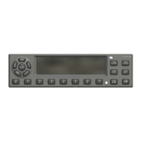
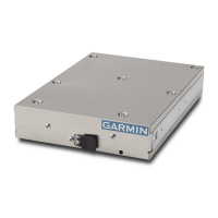
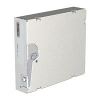
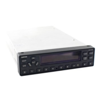
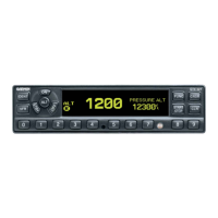
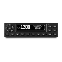
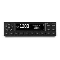
Details the features and models of the GTX 3X5 transponder units.
Lists and defines technical terms and acronyms used throughout the manual.
Describes the Automatic Dependent Surveillance-Broadcast (ADS-B) functions of the transponder.
Explains the Flight Information Services-Broadcast (FIS-B) capabilities of the GTX 345.
Details the Traffic Information Service (TIS) capabilities of the GTX 335.
Summarizes the input/output interfaces supported by GTX 335 and GTX 345.
Lists physical characteristics and operating specifications for panel and remote mount units.
Provides detailed specifications for the transponder transmitter and receiver.
Lists specifications for the Universal Access Transceiver (UAT) receiver.
Lists specifications for the 1090 MHz receiver.
Details specifications for the internal GPS receiver.
Outlines power requirements and current draw for different GTX 3X5 models.
Lists the TSO compliance and functions for the GTX 3X5 transponder.
Explains FCC transmitter licensing requirements for operating the GTX 3X5.
Lists other relevant documents for installing the GTX 3X5.
States limitations regarding HSDB interface approval for hazardous/catastrophic failure data.
States limitations on using ARINC 429 data for hazardous/catastrophic functions.
Provides an overview of installation information and general procedures.
Details different models and configurations of the GTX 3X5 transponder.
Lists the accessories included with various GTX 3X5 unit kits.
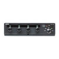
Describes optional accessories like GAE module, GX000 rack, and vertical remote mount.
Lists materials and accessories required for installation but not provided by Garmin.
Lists special tools needed for installation, including crimp tools.
Provides requirements and approved antennas for the transponder.
Details requirements and approved antennas for the internal GPS receiver.
Outlines minimum system configurations for compatible displays and control panels.
Explains how the GTX 3X5 prioritizes data inputs from multiple sources.
Discusses considerations for mounting transponder and GPS antennas for optimal performance.
Provides instructions for installing wire harnesses and building wire connections.
Lists parts required for backshell and ground adapter assemblies.
Details the procedures for preparing shielded cables for connection.
Guides through the process of assembling connectors and backshells.
Explains how to install the configuration module and GAE module.
Provides instructions for routing and installing coaxial cables.
Covers installation procedures for panel mount, remote mount, and G1000 racks.
Details the installation and removal steps for panel and standard remote mount units.
Explains the installation and removal process for vertical remote mount units.
Provides pinout details for the main board connector (J3251).
Lists pinout details for the ADS-B board connector (J3252) on GTX 345.
Details power pins, configuration, and control inputs for the GTX 3X5.
Explains the lighting bus input for panel brightness control.
Describes the different sources for pressure altitude inputs.
Details the discrete input/output functions and their configuration.
Covers RS-232, ARINC 429, HSDB, and RS-422 serial data interfaces.
Explains the interface and function of the configuration module.
Describes the USB interface for configuration, updates, and service.
Outlines the required configuration and checkout procedures.
Covers essential checks for mounting, wiring, and power application before energizing the unit.
Explains how to enter configuration mode and navigate settings.
Details how to configure audio output, volume, and alert types.
Covers configuration of RS-232, ARINC 429, discrete, and HSDB interfaces.
Describes various unit settings like FIS-B, altitude, temperature, and ID.
Explains how to adjust display backlight, minimum level, and keypad settings.
Covers configuration for OAT sensor, altitude sources, GPS sources, and AHRS.
Details configuration settings for ADS-B Out and In capabilities.
Explains how to access diagnostic information for troubleshooting.
Refers to a separate guide for remote unit configuration.
Provides steps for performing ground checks on GPS reception.
Details ground checks required for transponder operation.
Refers to a separate guide for software installation.
Describes the RS-232 electrical interface and data formats for air data input.
Explains the 10-byte message format for altitude data.
Details the 17-byte message format for altitude data from GAE modules.
Describes message strings received from the air data computer.
Lists ARINC 429 input formats for AHRS, ADC, and ARINC 743A data.
Outlines ARINC 429 output formats for GPS data and traffic information.
Illustrates the GTX 3X5 GPS panel mount assembly and its components.
Provides dimensional data and center of gravity for panel mount units.
Shows the GTX 3X5R GPS standard remote mount assembly and its parts.
Gives dimensions and center of gravity for standard remote mount units.
Illustrates the GTX 3X5 vertical remote mount assembly and components.
Provides dimensional data for vertical remote mount units.
Shows the GTX 3X5R GPS G1000 mount rack assembly.
Details dimensions and center of gravity for G1000 mounting racks.
Shows the panel cutout dimensions for installing the GTX 3X5 unit.
Identifies the locations of connectors and vents on the GTX 3X5 unit.
Illustrates the optional Garmin Altitude Encoder.
Lists compatible ADS-B In displays and their configuration settings.
Details compatible GPS sources and their interface configurations.
Lists compatible altitude sources and their configuration settings.
Lists compatible audio panels and their configuration.
Lists compatible radar altimeters and their configuration.
Lists compatible heading reference sources and their configuration.
Lists compatible traffic sensors for the GTX 345.
Details Bluetooth compatibility and configuration for the GTX 345.
Lists compatible remote control units and their configurations.
Lists compatible TIS-A displays and their configurations.
Shows typical power connections for the GTX 3X5.
Illustrates interconnect wiring between GTX 345 and G1000 systems.
Shows interconnect wiring between GTX 335 and G1000 systems.
Details interconnect wiring between GTX 3X5 and GNS 480 (CNX80).
Illustrates typical interconnect wiring for GTX 335 to GTN 6XX/7XX.
Shows interconnects for single/dual GTX 335 with GTN 6XX/7XX.
Illustrates typical interconnect wiring for GTX 345 to GTN 6XX/7XX.
Shows interconnects for single/dual GTX 345 with GTN 6XX/7XX.
Details interconnect wiring between GTX 335/345 and GDL 88.
Illustrates interconnect wiring for GTX 345 with traffic sensors.
Shows interconnects for GTX 345 with GNS 400W/500W series.
Details interconnect wiring for audio signals to the GTX 3X5.
Illustrates interconnect wiring for radio altimeter input to the GTX 3X5.
Shows interconnect wiring for AHRS and heading sources to the GTX 3X5.
Details interconnects for switches and OAT probe to the GTX 3X5.
Illustrates interconnect wiring for various altitude sources to the GTX 3X5.
Shows interconnect wiring for GTX 335 with GNS 400W/500W series.
Details interconnect wiring for GTX 345/345R with Flight Stream.
Illustrates interconnect wiring for GTX 345 with MX20/GMX 200.
Shows interconnect wiring for GTX 335 with GDU 620.
Details CS-ACNS compliance for Elementary Surveillance (ELS) functions.
Outlines CS-ACNS compliance for Enhanced Surveillance (EHS) functions.
Lists CS-ACNS compliance standards for ADS-B Out functionality.
| Brand | Garmin |
|---|---|
| Model | GTX 3X5 Series |
| Category | Marine Radio |
| Language | English |