Do you have a question about the Garmin GTX 320A and is the answer not in the manual?
Provides installation and operating instructions for GTX 320/320A.
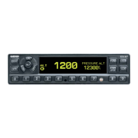
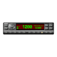
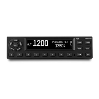
Describes the GTX 320/320A transponder's function and capabilities.
Details electrical and performance specifications for the transponder.
Lists the technical specifications for the transponder unit.
Provides physical dimensions and weight for the GTX 320.
Provides physical dimensions and weight for the GTX 320A.
Lists available transponder models and associated part numbers.
Details the different configurations and part numbers for the transponder.
Lists optional accessories required for installation.
Specifies necessary supplementary equipment for installation.
Outlines requirements for FAA approval of aircraft installations.
Details testing procedures for ATC transponders per FAA regulations.
Describes the product warranty terms and conditions.
Introduces installation procedures and compliance with regulations.
Provides instructions for safely unpacking and inspecting the unit.
Covers antenna placement considerations and installation guidelines.
Details optimal placement criteria for the transponder antenna.
Instructions for installing the antenna per manufacturer and FAA guidelines.
Addresses FAA approval for antenna installations on pressurized aircraft.
Provides precautions for routing antenna cables.
Describes connector types and installation for antenna cables.
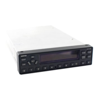
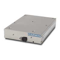
Details the physical installation process of the transponder unit into a rack.
Explains how to make electrical connections using the D-subminiature connector.
Advises on checking existing installation components before adapter use.
Describes installation using a Narco AT 150 rack with an adapter.
Describes installation using a Bendix/King rack with an adapter.
Details FCC licensing requirements for operating the transponder.
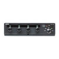
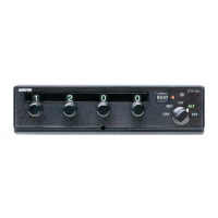
Explains the basic operation and controls of the transponder.
Describes the five positions of the function selector switch.
Explains how to select identification codes and precautions.
Details the function and use of the IDENT button.
Explains the function of the reply light indicator.
Provides guidance for continued airworthiness documentation.
Defines the scope and purpose of the ICA document.
Describes the transponder installation as a major alteration.
Refers to the Pilot's Guide for control and operation details.
States that servicing information is not applicable.
Specifies that maintenance is 'on condition' only.
Refers to Maintenance Manuals for troubleshooting.
Refers to Section 2.4 for removal/reinstallation.
Refers to Appendix B for diagrams.
States that no special inspection requirements exist.
States that no protective treatments are applicable.
Refers to AC43.13 for fastener data.
States that no special tools are required.
Applies specific sections to commuter aircraft.
States no overhaul time limitations.
States no airworthiness limitation section.
Describes the process for revising the ICA.
Mentions resources for assistance with ICA.
Details the environmental tests conducted for the GTX 320.
Details the environmental tests conducted for the GTX 320A.
Lists the available assembly and installation drawings.
| Type | Transponder |
|---|---|
| Frequency | 1090 MHz |
| Dimensions | 6.25"W x 1.3"H x 9.5"D (15.9 x 3.3 x 24.1 cm) |
| Weight | 2.2 lbs (1.0 kg) |
| Interface | RS-232 |
| Operating Temperature | -20°C to +55°C |
| Transmit Power | 250 W |
| Power Output | 250 W |