Do you have a question about the Garmin GTX 3X5 and is the answer not in the manual?
Manual provides mechanical and electrical information for GTX 3X5 installation.
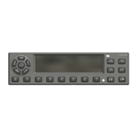
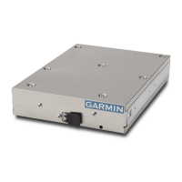
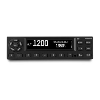
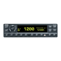
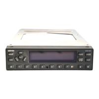
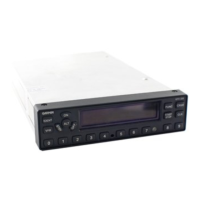
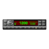
Describes GTX 3X5 models, including transponders and optional GPS.
Lists and defines abbreviations and acronyms used in the document.
Details ADS-B Out and ADS-B In capabilities of the GTX 3X5 units.
Explains FIS-B information reception from UAT ground stations.
Describes how GTX 335 supplies traffic information via FAA radar-based TIS.
Summary of interfaces and I/O quantities for GTX 335 and GTX 345.
Lists physical characteristics, operating range, altitude, and audio output specs.
Details transponder frequency, power, receiver sensitivity, and suppression.
Lists frequency, modulation, data rate, and sensitivity for UAT receiver.
Details frequency, modulation, data rate, and sensitivity for 1090 MHz receiver.
Lists GPS channels, frequency, sensitivity, accuracy, and datum.
Details input voltage, power, and current requirements for GTX 3X5 units.
Outlines TSO compliance and lists functions evaluated under TSO.
Discusses FCC regulations and licensing requirements for the UHF transmitter.
Lists additional documents for GTX 3X5 installation and technical information.
GTX 345 HSDB interface not approved for hazardous failure data.
ARINC 429 data must not be used for functions classified as hazardous failure.
Info on installing GTX 3X5 and accessories, following aviation procedures.
Details the different configurations available for the GTX 3X5 units.
Lists the items included with each GTX 3X5 unit kit.
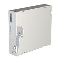
Describes optional accessories like GAE, GX000 Rack, and Vertical Remote Mount.
Details requirements and types of GPS antennas for GTX 335/345 with internal GPS.
Lists essential materials and accessories not included with the GTX 3X5.
Lists special tools required for connector and contact crimping.
Discusses UHF antenna requirements and acceptable models for GTX 3X5/3X5R.
Lists antenna specifications for optimal performance with internal GNSS receiver.
Details necessary components for various GTX 3X5 models for ADS-B/FIS-B displays.
Explains how the GTX 3X5 selects data from multiple sources based on priority.
Lists parameters received from internal and external GPS receivers.
Provides guidance on mounting location for transponder and GPS antennas.
Ensures transponder and GPS antennas are electrically bonded to the aircraft.
Covers considerations for installing wiring according to AC 43.13-1B.
Details requirements for achieving a proper electrical bond for equipment.
States that no cooling requirements exist for the GTX 3X5.
Details how to install pins into connectors and build a wire harness.
Lists parts included in connector kits for backshell assemblies.
Explains how to prepare shielded cables for termination to the connector backshell.
Provides step-by-step instructions for assembling connectors and backshells.
Details the installation of the configuration module for unit settings.
Outlines steps for routing, attaching, trimming, and connecting coaxial cables.
Instructions for installing panel mount and remote mount units into racks.
Procedure for installing and removing panel and standard remote mount units.
Procedure for installing and removing vertical remote mount units.
Details pin assignments and I/O for the main board connector (P3251).
Details pin assignments and I/O for the ADS-B board connector on GTX 345.
Describes power inputs, aircraft power, ground, and switched power outputs.
Explains how the lighting bus input controls display/keypad brightness.
Lists various sources for pressure altitude input, including Gray code and GAE.
Describes active-low discrete inputs and configurable discrete outputs.
Details RS-232, ARINC 429, HSDB, and RS-422 interface specifications.
Describes the external suppression connection for L-band equipment.
Details the OAT input for displays and temperature sensor specifications.
Describes the audio output for aural alerts and its capability.
Explains the use of TIME MARK as an output for 1PPS to other equipment.
Details the interface for configuration modules and optional GAE modules.
Explains the use of the USB interface for configuration and updates.
Outlines the required GTX 3X5 configuration and checkout procedures.
Details checks for wire harness, connections, and power before unit energization.
Explains how to enter configuration mode and navigate settings for panel mount units.
Sets audio output, volume, and alert types for the transponder.
Configures inputs/outputs for RS-232, ARINC 429, discretes, and HSDB interfaces.
Details settings for FIS-B, Altitude Units, Temperature Units, Installation ID, VFR ID.
Configures display backlight, keypad backlight, and photocell settings.
Configures OAT sensor, altitude sources, GPS sources, integrity, and offsets.
Configures aircraft category, airspeed, length, width, and ADS-B In/Out settings.
Provides information for troubleshooting, including input states and channel status.
Details using the GTX 3X5 Install Tool via USB for unit configuration.
Procedure for checking GPS reception and LAT/LON accuracy on the ground.
Instructions for downloading and installing software using the GTX 3X5 Install Tool.
Details electrical interface and altitude/airdata message formats for RS-232.
Lists compatible ADS-B In displays and their configuration settings.
Details compatible GPS sources and their interface configurations.
Lists compatible altitude sources and their configuration settings.
Lists compatible audio panels and their GTX 3X5 configuration settings.
Lists compatible radar altimeters and their GTX 3X5 configuration.
Lists compatible heading reference sources and their configurations.
Lists compatible traffic sensors for the GTX 345 and their configurations.
Details Bluetooth compatibility and configuration settings.
Lists compatible remote control units and their configurations.
Lists compatible TIS-A displays and their configurations.
| Brand | Garmin |
|---|---|
| Model | GTX 3X5 |
| Category | Marine Radio |
| Language | English |