Do you have a question about the Garmin GWX 68 and is the answer not in the manual?
Defines the radiation zone exceeding the US Government standard of 1 mW/cm².
Precautions to prevent possible human body damage from radar operation.
Prohibits radar operation during refueling or defueling to prevent fuel ignition.
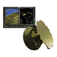
Presents mechanical and electrical installation requirements for the GWX 68 Airborne Weather Radar.
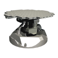
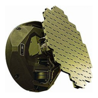
Describes the GWX 68 Airborne Weather Radar as a microprocessor-based Line Replaceable Unit (LRU).
Details the GWX 68's open architecture system using ARINC 429, ARINC 453, and Ethernet interfaces.
Covers physical, general, performance, and power requirements for the GWX 68 unit.
Explains FCC licensing requirements for radio station operation of the GWX 68.
Details TSO/ETSO compliance standards and aircraft installation approval requirements.
Lists supporting publications for installation, including G1000 and MX20 manuals.
Outlines the two-year warranty terms and conditions for Garmin products.
Provides hardware equipment information for installing the GWX 68, related hardware, and antennas.
Lists available part numbers for the GWX 68 unit and standard installation kit.
Discusses mechanical and electrical practices for installation, including antenna considerations for pressurized aircraft.
Details wire gauge, connector compatibility, routing, and EMI/heat considerations for installation.
Addresses thermal characteristics and the need for ventilation or convection for product longevity.
Specifies mounting surface requirements for structural support and electrical bonding for EMI protection.
Instructions for unpacking, inspecting for damage, and handling shipping containers.
Guidance on fabricating and installing wiring harnesses, connectors, and strain relief per FAA standards.
Procedure for assembling backshells and D-Subminiature connectors, including shield block installation.
Details rigid mounting in aircraft nose section, pod mounting, and alignment requirements.
Explains the need for post-installation configuration and checkout procedures for valid output.
Provides information on continued airworthiness instructions and 'on condition' maintenance.
Lists pin functions and I/O for the P400 connector on the GWX 68 unit.
Details aircraft power input requirements and remote on/off functions for the GWX 68.
Describes electrical characteristics for ARINC 429/453 and Ethernet HSDB serial data interfaces.
Covers configuration module details, including ground, data, power, and clock connections.
Explains flight instrument inputs for pitch and roll attitude from AFCS.
Provides dimensional drawings and mounting details for the GWX 68 antenna unit.
Illustrates typical wiring connections between GWX 68 and G1000 system.
Shows typical wiring connections between GWX 68 and MX20 unit.
Depicts wiring for analog stabilization inputs and outputs for the GWX 68.
Illustrates wiring for AHRS stabilization inputs and outputs for the GWX 68.
| Operating Voltage | 12-24 VDC |
|---|---|
| IP Rating | IPX6 |
| Type | Solid-state Doppler |
| Display Size | Garmin chartplotters |
| Frequency | X-band |
| Radar Type | Solid State |
| Rotation Speed | 24 rpm |
| Display Compatibility | Garmin chartplotters |