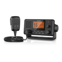
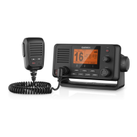
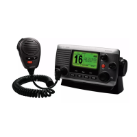
VHF 110/210 AIS Series
Installation Instructions
Important Safety Information
WARNING
See the Important Safety and Product Information guide in the product box for
product warnings and other important information.
CAUTION
Always wear safety goggles, ear protection, and a dust mask when drilling,
cutting, or sanding.
NOTICE
When drilling or cutting, always check what is on the opposite side of the
surface.
Registering Your Device
Help us better support you by completing our online registration today.
• Go to http://my.garmin.com.
• Keep the original sales receipt, or a photocopy, in a safe place.
Contacting Garmin
®
Product Support
• Go to www.garmin.com/support for in-country support information.
• In the USA, call 913-397-8200 or 1-800-800-1020.
• In the UK, call 0808 238 0000.
• In Europe, call +44 (0) 870 850 1241.
Mounting Considerations
NOTICE
This device should be mounted in a location that is not exposed to extreme
temperatures or conditions. The temperature range for this device is listed in
the product specifications. Extended exposure to temperatures exceeding the
specified temperature range, in storage or operating conditions, may cause
device failure. Extreme-temperature-induced damage and related
consequences are not covered by the warranty.
When selecting a mounting location, you should observe these considerations.
• The location should provide optimal viewing as you operate your boat.
• The location should allow for easy access to all device interfaces, such as
the keypad, touchscreen, and card reader, if applicable.
• The location must be strong enough to support the weight of the device
and protect it from excessive vibration or shock.
• To avoid interference with a magnetic compass, the device should not be
installed closer to a compass than the compass-safe distance value listed
in the product specifications.
• The location must allow room for the routing and connection of all cables.
Antenna Mounting and EME Exposure
WARNING
Radio operators with cardiac pacemakers, life-support machines, or electrical
medical equipment should not be exposed to excessive radio-frequency (RF)
fields, because the RF field may interfere with the function of their medical
equipment.
CAUTION
This device generates and radiates radio frequency (RF) electromagnetic
energy (EME). Failure to observe these guidelines may expose people to RF
radiation absorption exceeding the maximum permissible exposure (MPE).
Garmin declares a MPE radius of 2.48 m (97.64 in.) for this system, which was
determined using 25 W output to an omni-directional, 6 dBi gain antenna. The
antenna should be installed to maintain a distance of 2.48 m (97.64 in.)
between the antenna and all people.
Bail Mounting the Device
NOTICE
If you are mounting the bracket on fiberglass with screws, it is recommended
to use a countersink bit to drill a clearance counterbore through only the top
gel-coat layer. This will help to avoid cracking in the gel-coat layer when the
screws are tightened.
Stainless-steel screws may bind when screwed into fiberglass and
overtightened. It is recommended to apply an anti-seize lubricant on the
screws before installing them.
You can use the included bracket to bail mount the device on a flat surface.
1
Using the bail-mount bracket
À
as a template, mark the pilot holes.
2
Using a 3.5 mm (
9
/
64
in.) drill bit, drill the pilot holes.
3
Using the included screws
Á
, secure the bail-mount bracket to the
mounting surface.
4
Install the bail-mount knobs
Â
on the sides of the device.
5
Place the device in the bail-mount bracket and tighten the bail-mount
knobs.
Flush Mounting the Device
NOTICE
Be careful when cutting the hole to flush mount the device. There is only a
small amount of clearance between the case and the mounting holes, and
cutting the hole too large could compromise the stability of the device after it is
mounted.
If you are mounting the bracket on fiberglass with screws, it is recommended
to use a countersink bit to drill a clearance counterbore through only the top
gel-coat layer. This will help to avoid cracking in the gel-coat layer when the
screws are tightened.
Stainless-steel screws may bind when screwed into fiberglass and
overtightened. It is recommended to apply an anti-seize lubricant on the
screws before installing them.
The included template and hardware can be used to mount the device in your
dashboard.
1
Trim the template and make sure it fits in the location where you want to
mount the device.
2
Using a 9.5 mm (
3
/
8
in.) drill bit, drill one or more of the holes inside the
corners of the solid line on the template to prepare the mounting surface
for cutting.
3
Using a jigsaw or rotary tool, cut the mounting surface along the inside of
the solid line indicated on the template.
4
Place the device in the cutout to test the fit.
5
If necessary, use a file and sandpaper to refine the size of the cutout.
January 2017
Printed in China 190-02061-02_0A