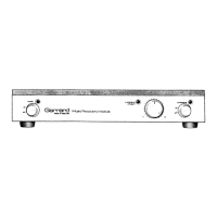
Model MRMIOI Music Recovery Module
Introduction
The Music Recovery Module (referred to as MRM) is designed
to remove the objectionable noises heard when a phono
pickup meets
a
scratch on the record being played.
The MRM is not intended to remove all noises associated with
old,
worn or generally dirty records. Since these noises occur
in an almost continuous manner, their detection could lead to
the removal of
a
substantial proportion of the original
recording.
The MRM contains
a
high quality stereo pre-amplifier with
magnetic phono inputs. This allows the MRM to be simply and
directly connected to the amplifier 'auxiliary' or 'tuner' inputs.
The scratch detection circuit recognises the whole waveform of
the scratch and distinguishes it from the peaks of the recorded
music. In order to allow the scratch detection circuit sufficient
time to make the decision to remove the scratch, the channels
are individually delayed by
a
few miUi-seconds without limiting
the audio frequency range.
After recognising the scratch, a specially designed network
isolates the signal for sufficient time for the scratch noise to
pass out of the delay line.
Patents applied for.
WARNING: To prevent fire or shock hazard, do not expose this
appliance to rain or moisture.
Specifications
Input
Suitable for pickup cartridges having an output of 0.7 to
2mV7cm/sec.
Input impedance
47k ohm.
Frequency response
± 1.5dB
2OH2
to 20kHz (including equalisation network for
magnetic cartridges).
Dynamic range
Direct mode: greater than 100dB.
Via suppressor: greater than 80dB (typically 85dB).
(Unweighted 20Hz to 20kHz ref. to 1kHz maximum output.)
Distortion
At 1kHz at nominal output:
Direct mode: Typically less than
0.01
%
T.H.D.
Via suppressor: Typically less than
0.1
%
T.H.D.
Channel balance
Better than 2dB at 1kHz.
Nominal output
300mV RMS.
Output
For
1%
T.H.D. at 1kHz:
Suppressor 'in' 2.5V rms.
Suppressor 'out' 8V rms.
Output impedance
3.3k ohm.
Rated load impedance
Greater than 10k ohm (short circuit protected).
Power supply
120V
AC,
50/60HZ 7VA, or 220/240V, AC 50/60Hz 7VA.
Dimensions
378mm x 298mm x 71mm (W x D x H).
Shipping weight
3.7kg
(8.161b).
Garrard's policy is one of continued development and
therefore the Company reserves the right to alter specifications
without notice.
For Service and Enquiries:
Garrard Engineering Limited,
Sales Service Department,
Kembrey Street,
Swindon,
Wiltshire SN2 6BP.
Telephone: Swindon (0793)41701
Or, in
U.S.A.:
Plessey Consumer Products,
Garrard Dealer Sales Division,
100 Commercial Street,
Plainview, New York 11803.
Telephone: (516)938-8900
Connections
Connecting to the power supply
The power supply lead enters at the right hand side of the rear
panel.
Important: Before connecting to the power supply ensure by
the voltage instruction label on the back panel that the MRM is
suitable for the supply voltage.
1.
United Kingdom only. A power supply plug is not fitted and
as the colours of the wires in the mains lead of
the
MRM
may not correspond to the colours identifying the terminals
in your power supply plug proceed
as
follows:
The BROWN wire must be connected to the terminal in the
plug marked V or coloured red.
The BLUE wire must be connected to the terminal in the
plug marked 'N' or coloured black.
A separate earth wire is not required.
If
a
13 amp (BS1363) plug is
used,
fit
a
3 amp or
5
amp fuse.
For any other type of plug protect with a 5 amp fuse or fuse
wire in the adaptor or distributor board.
2.
Europe and
U.S.A.
A suitable
2
pin plug is provided for
connection to the power supply.
Connections at the rear panel
Connections at the rear panel of the MRM are both RCA and
DIN type input and RCA type output sockets to provide the
facility to link up to any equipment likely to be used with it.
European versions also have
a
DIN type output socket.
The RCA connectors are identified L (left) and
R
(right), so that
a signal into the
R
connector appears after processing on the
R
output connector.
For convenience, the pickup input and the amplifier output
connections are placed at either side of the signal earth ( -t )
terminal respectively.
It may be found advantageous to connect
a
lead between the
amplifier or record player
and
the MRM signal earth terminals,
to minimise hum.
Audio connecting leads (U.K. and Europe)
The MRM is supplied with an audio connecting lead specially
wired with a
5-pin
DIN type plug at one end and
RCA
type
J
 Loading...