phono plugs at the other. (Part
No.
606/7/79486/001.)
MRM Input: Transfer the amplifier
end
of
the
signal lead
between the record player and the amplifier to the
MRM,
using,
(
as appropriate, the DIN input socket or the RCA phono input
sockets, observing the
R
and L channel identification markings.
MRM Output: Connection to the amplifier from the MRM will
be to the following colour coding:
Black or Brown plug (RCA) - Socket
R
(right)
White or Grey plug (RCA) - Socket L (left)
If the amplifier has
a
5-way
DIN
input socket:
1.
Attach the 5 pin DIN type plug on the Garrard audio
connection lead to this.
2. Attach the RCA type phono plugs on the other end of the
lead to the appropriate output sockets on the MRM,
observing the
R
and L channel identification markings.
If the amplifier has RCA type phono input sockets:
1.
Attach the phono plugs on the Garrard audio connection
lead to these, observing the
R
and
L
channel identification
markings.
2.
Attach the 5 pin DIN type plug on the other end of the lead
to the MRM DIN output socket
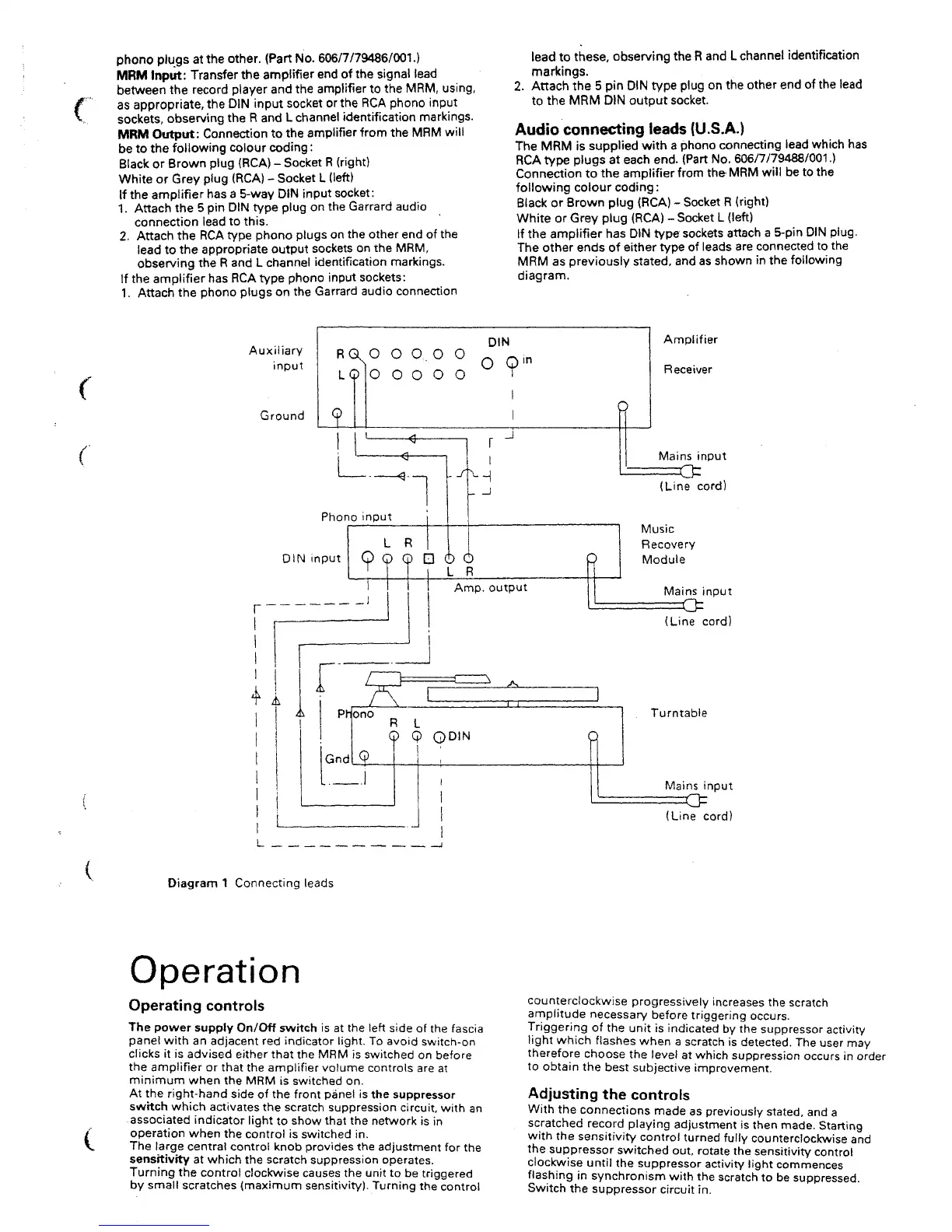
Audio connecting leads (U.S.A.)
The MRM is supplied with a phono connecting lead which has
RCA
type plugs at each end. (Part No. 606/7/79488/001.)
Connection to the amplifier
from
theMRM will be to the
following colour coding
:
Black or Brown plug (RCA) - Socket
R
(right)
White or Grey plug (RCA) - Socket L (left)
If the amplifier has DIN type sockets attach
a
5-pin
DIN
plug.
The other ends of either type of leads are connected to the
MRM as previously
stated,
and as shown in the following
diagram.
Auxiliary
input
Ground
DIN
RQ
N° OQ.O O
0
Q,
n
LQ O O O O O
o
- -f
Phono input
DIN input
I
_l
Amplifier
Receiver
P
Amp.
output
Mains input
(Line cord)
Music
Recovery
Module
Mains input
(Line cord)
Q
Turntable
Mains input
(Line cord)
Diagram
1
Connecting leads
Operation
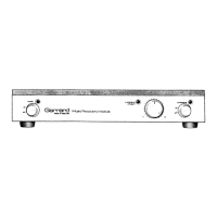
Operating controls
The power supply On/Off switch is at the left side of the fascia
panel with an adjacent red indicator light. To avoid switch-on
clicks it is advised either that the MRM is switched on before
the amplifier or that the amplifier volume controls are at
minimum when the MRM is switched on.
At the right-hand side of the front panel is the suppressor
swttch which activates the scratch suppression circuit, with an
associated indicator light to show that the network is in
operation when the control is switched in.
The large central control knob provides the adjustment for the
sensitivity at which the scratch suppression operates.
Turning the control clockwise causes the unit to be triggered
by small scratches (maximum sensitivity). Turning the control
counterclockwise progressively increases the scratch
amplitude necessary before triggering occurs.
Triggering of the unit is indicated by the suppressor activity
light which flashes when a scratch is detected. The user may
therefore choose the level at which suppression occurs in order
to obtain the best subjective improvement.
Adjusting the controls
With the connections made as previously
stated,
and a
scratched record playing adjustment is then made. Starting
with the sensitivity control turned fully counterclockwise and
the suppressor switched out, rotate the sensitivity control
clockwise until the suppressor activity light commences
flashing in synchronism with the scratch to be suppressed.
Switch the suppressor circuit in.
 Loading...