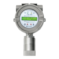
4.1. Components of transmitter
No ITEMS SPECIFICATION
9 Power lamp Lamp is lighted when .power switch is turned On
10 Trouble lamp Lighted when abnormality occurs in circuit or sensor sensitivity, etc.
11 Alarm1 lamp Lighted when gas is leaked to become higher than Alarm1 level
12 Alarm2 lamp Lighted when gas is leaked to become higher than Alarm2 level
13 Function key
When contact is made for more than 2sec by using Magnet-bar upon parameter setting, it is
converted to Program mode. (Program mode, Calibration mode, Test mode, etc.) Also, it is
used when Data is inputted for setting.
14 Reset key
Converted when cancelled during parameter setting or touched for more than once by using
Magnet bar to return to the previous state. (Converted to the previous mode by one stage at
a time upon every touch.
15 ↑(Up) key
Converted or transformed by one stage at a time when touched once by using Magnet-bar
upon mode conversion or figure transformation (transformed to the higher stage)
16 ↓(Down) key
Converted or transformed by one stage at a time when touched once by using Magnet-bar
upon mode conversion or figure transformation(transformed to the lower stage)
17 External earth
- Outside grounding for protection from outside noise or strong electric field
- For grounding cable, use conductor larger than 4mm upon coupling connection
18 Mount hole Hole to mount Gas Detector onto outer wall and other installation place.
19 Cover fixed screw(M4)
Fix with a hexagonal lens bolt to prevent drop-off due to outside impacts after assembly of
Detector Housing Body and Detector Housing Cover
20 Sensor thread Mounting port for mounting of infrared gas sensor (Detector)
21 Cable inlet
Basically PF 3/4" is provided for power supply to Gas detector and lead-in of measurement
output signals upon installation operation.
22 Internal earth
- Inside grounding of Detector for protection from outside nose or strong electric field
- For grounding cable, use conductor larger than 4mm upon coupling connection.
23
RS-485 Module /
HART Module
Connector to connect Isolation Type RS-485 communication Module for communication with
PC or PLC and HART communication Module. For RS-485 communication, communication
Address should be set, and the basic value is set for No.1. For HART communication,
Polling-Address and Tag No. etc. should be set. (Optional specifications)
24
Relay Contact
Type Selection
Configured so as to allow selection of A, B contact. If not in ENERGIZER MODE, it operates
as contact A (Normal Open) when Jumper is connected to the part displayed as silk A, while
it operates as contact B (Normal Close) when Jumper is connected to the part displayed as
silk B. On the contrary, if in ENERGIZER MODE, it operates as contact B when Jumper is
connected to A, while it operates as contact A when Jumper is connected to B.
25
Warning Light
Connector
Connecting connector when the warning light is used(Optional)
[Table 1. Description on components of GIR-3000 transmitter]
4. Name and description of each part
GIR-3000
Instruction Manual
 Loading...