www.gastron.com
08
_
09
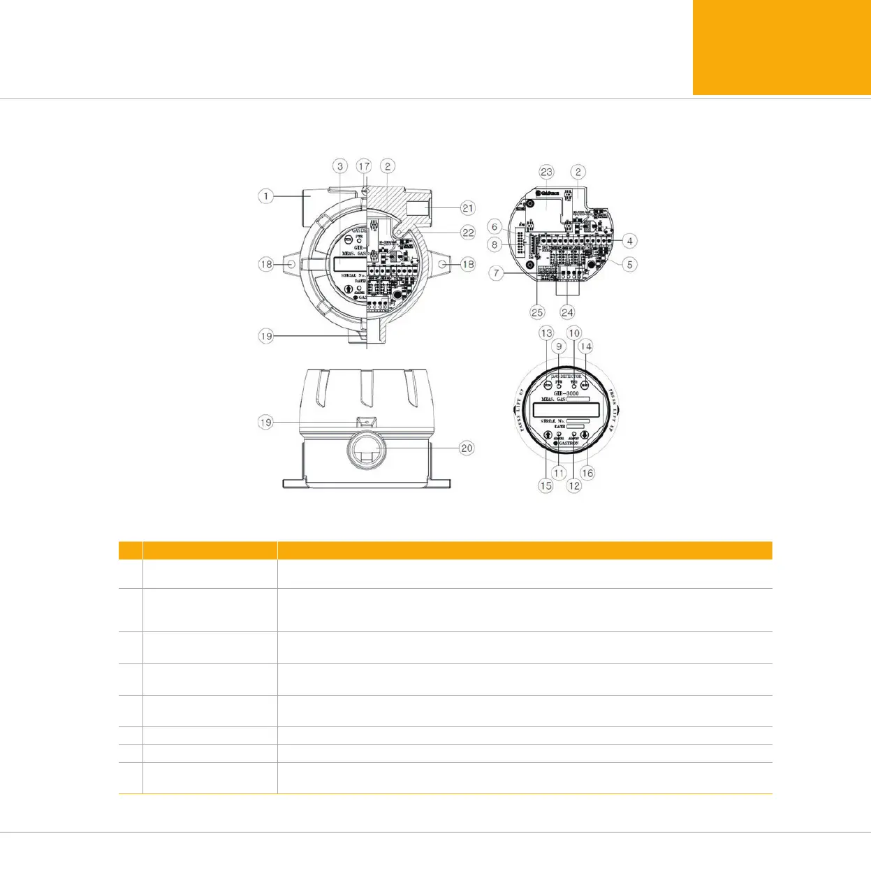
4. Name and description of each part
4.1. Components of transmitter
No ITEMS SPECIFICATION
1 Housing
Protect PCB Board embedded inside Sensor and Housing from change of
outside environments and impact.
2 Main PCB
Amplify output signals produced by Sensor, and convert to standard output of DC 4~20mA for
transmission, and output Isolation RS- 485 communication Signal and Alarm relay contact signal.
Also, send Data to be displayed in Display unit.
3 Display PCB
Display Data received from MAIN PCB in LCD or OLED, and
display the current Event situations by Power lamp, Alarm lamp, Trouble lamp
4
Power/Signal
Terminal
CN12 is comprised of power supply of DC18-31V and DC 4~20mA standard output Connection
terminal (VISO, +V, mA, -V, ETH).
5
Alarm signal
Terminal
CN8 is Alarm signal connection terminal, as a terminal where Trouble, Alarm1, Alarm2 Relay
contact are outputted.
6 RS-485 signal CN3 is Isolation RS-485 communication signal connection terminal(A, B).
7 Sensor terminal CN10 is Sensor connection terminal. (RD, WH, BK, BE)
8
Program Downloading
Connector
Connector that allows downloading of product program.
[Figure 2. Components of GIR-3000]
 Loading...