
J
Jordan RoblesAug 18, 2025
What to do if GASTRON Gas Detectors show '>VIN LOW VOLTAGE'?
- AAaron HillAug 18, 2025
If your GASTRON Gas Detectors display a '>VIN LOW VOLTAGE' error, verify the input power. The normal voltage level should be 24V.
What to do if GASTRON Gas Detectors show '>VIN LOW VOLTAGE'?
If your GASTRON Gas Detectors display a '>VIN LOW VOLTAGE' error, verify the input power. The normal voltage level should be 24V.
What to do if GASTRON Gas Detectors display FAULT8?
If your GASTRON Gas Detectors display FAULT8, recalibration is required.
What to do if GASTRON Gas Detectors display FAULT5 'SEN-CHANGE(DET)'?
If your GASTRON Gas Detectors show FAULT5 'SEN-CHANGE(DET)', the cause might be a fault in the gas sensor. Check the filter and waveguide of sensing part (GSA-920A).
What to do if GASTRON Gas Detectors display FAULT6 'SEN-CHANGE(REF)'?
If your GASTRON Gas Detectors show FAULT6 'SEN-CHANGE(REF)', the cause might be a fault in the gas sensor. Check the filter and waveguide of sensing part (GSA-920A).
What to do if GASTRON Gas Detectors display FAULT7 'SEN-CHANGE(OPT)'?
If your GASTRON Gas Detectors show FAULT7 'SEN-CHANGE(OPT)', the cause might be a fault in the gas sensor. Check the filter and waveguide of sensing part (GSA-920A).
What does it mean if GASTRON Gas Detectors show FAULT4 'SEN-COM T/O'?
If your GASTRON Gas Detectors display FAULT4 'SEN-COM T/O', it indicates a connection fault in the CN6 sensor terminal or a fault in the sensing part (GSA-920A).
What to do if GASTRON Gas Detectors display FAULT9 'SEN-D,RCH LOW'?
If your GASTRON Gas Detectors show FAULT9 'SEN-D,RCH LOW', the cause might be a fault in the gas sensor. Check the filter and waveguide of sensing part (GSA-920A).
What to do if GASTRON Gas Detectors display FAULT10 '>SEN-EMPERATURE'?
If your GASTRON Gas Detectors display FAULT10 '>SEN-EMPERATURE', the cause is a fault in the temperature sensor. Check the ambient temperature.
What does it mean if GASTRON Gas Detectors display FAULT0 'TSM-MEM C/S'?
If your GASTRON Gas Detectors display FAULT0 'TSM-MEM C/S', it indicates a fault in the Transmitter PCB MPU (U1).
What does it mean if GASTRON Gas Detectors display FAULT1 'TSM-EEPROM'?
If your GASTRON Gas Detectors display FAULT1 'TSM-EEPROM', it indicates a fault in the Transmitter PCB EEPROM (U4).
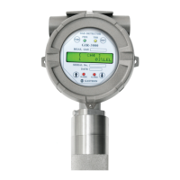
Overview of the GIR3000 IR gas detector for preventing accidents due to gas leaks.
Description of the GIR3000's explosion-proof aluminum alloy body and internal components.
Detailed specifications including measuring type, range, accuracy, operating conditions, and outputs.
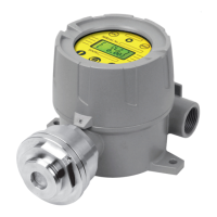
Visual identification and list of main components of the GIR3000 gas detector.
Explanation of the function and purpose of each component of the GIR3000 device.
Procedure for safely separating the detector body from its cover.
Arrangement and identification of terminals and connectors on the Main PCB.
Details on the HART board connection and its role in the Main PCB assembly.
Description of terminal functions on the Main PCB, including wiring methods.
Methods for configuring relay drive types (De-Energized and Energized modes).
Wiring configuration for 4-20mA source drive type using PLC connection.
Wiring configuration for 4-20mA sink drive type using PLC connection.
Wiring diagrams for connecting the gas detector to various control units.
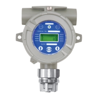
Outside view and dimensional drawings of the standard GIR3000 model.
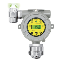
Outside view and dimensional drawings of the GIR3000 with a warning light.
Outside view and dimensional drawings of the GIR3000 with a raincover.
Flowchart and description for detector activation and key functions.
Description of the detector's state immediately after power application.
How the detector displays gas measurements and status in normal operation.
Guide on setting gas group, units, scale, and password.
Step-by-step guide for performing zero and span calibration.
Settings for alarm types, relay control, delay times, and alarm levels.
Procedures for testing trouble relay, alarm relay, and output signals.
How to view current values and status of the IR sensor.
Displaying hardware, software, and HART protocol versions.
Configuration options for sensor sensitivity, zero adjustment, and LED operations.
Setting up the detector's address for RS-485 communication.
Checking HART board status, polling address, and device information.
How inspectors can identify detector status and fault details.
Procedures for initializing factory data settings.
Procedures for initializing calibration data settings.
Table of fault codes, their descriptions, conditions, and recovery methods.
Recommendations for selecting installation sites based on safety regulations.
Important considerations and methods for safe and correct installation.
Record of changes and updates made to the instruction manual over versions.
| Protection Level | IP65 |
|---|---|
| Alarm Method | Audible and visual alarm |
| Humidity Range | 10% to 95% RH (non-condensing) |
| Output Signal | 4-20 mA |
| Operating Temperature | -20 ~ 60℃ |