RG66000889-REV.00 11
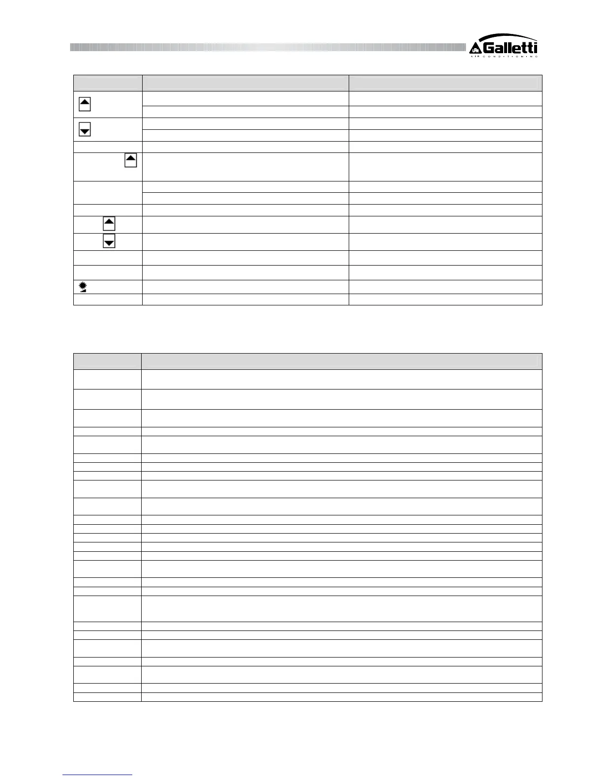
Button Status of the unit Effect after pressing the button
List of codes displays the codes of the parameters
Displays values increases value
List of codes displays the codes of the parameters
Displays values decreases value
PRG + SEL Normal operating condition after 5" password for FACTORY parameters
SEL +
Normal operating condition after 5" forces a manual defrosting cycle
Normal operating condition deletes alarms, if any
CLEAR
Hour counter hour counter reset immediately
PRG At start up default parameters
PRG +
At start up copies key on the unit's EEprom
PRG +
At start up copies key on the unit's EEprom
7
Normal operating condition selects heating mode (Heating)
Normal operating condition selects cooling mode (Cooling)
Always adjusts display contrast
MUTE Always silences the buzzer
3.6 Inputs and Outputs
Here below you will find the list of inputs/outputs with their relative connectors.
Connector Meaning
B1-GND
Evaporator inlet water temperature probe (water-water units)
Ambient air temperature probe (air-air units)
B2- GND
Evaporator outlet water temperature probe circuit1 (antifreeze)
Supporting heaters control probe (air-air units)
B3- GND
Condensation control probe circuit1 (for fans speed regulation in chiller mode or for the control of defrosting in heat
pump mode)
B4- GND Evap. outlet water temp. probe circuit 2 (antifreeze)
B5- GND
Condensation control probe circuit 2 (for fan speed regulation in chiller mode or for the control of defrosting in heat
pump mode)
ID1-IDCOM High pressure circuit 1
ID2-IDCOM Low pressure circuit 1
ID3-IDCOM Compressor overload circuit 1
ID4-IDCOM
Overload condenser fan circuit 1
Circuit 1 defrost end
ID5-IDCOM
Water flow detector (in water chillers)
Inlet fan overload (air-air)
ID6-IDCOM Remote ON/OFF
ID7-IDCOM Remote Cooling/Heating selection
ID8-IDCOM High pressure circuit 2
ID9-IDCOM Low pressure circuit 2
ID10-IDCOM Compressor overload circuit 2
ID11-IDCOM
Overload condensation- fan circuit 2
Circuit 2 defrost end
Y1-GND PWM analog output for condensation-removal fan circuit 1
Y2-GND PWM analog output for condensation-removal fan circuit 2
RES.1
Antifreeze heater circuit1 (water chillers)
Supporting heater / heating no.1 (air-air)
Compressor Tandem 2
COMP.1 Compressor circuit 1
VALVE 1 Reverse cycle valve circuit 1
PUMP
Water pump (water chillers)
Inlet air fan (air-air)
ALARM General alarm remote signal
RES.2
Antifreeze heater circuit 2 (water chillers)
Supporting heater / heating no. 2 (air-air)
COMP.2 Compressor circuit 2
VALVE 2 Reverse cycle valve circuit 2