RG66000889-REV.OO 4
Within the board itself you can also locate other four important areas:
• the SERIAL jumper for connection of an optional serial board for the interfacing to a supervisory and/or telemaintenance
centralized system
• the KEY jumper for connection of the optional board removable hardware key for the immediate on site programming of
all data
• P1÷P5 pin-strips for the function mode selection of the analog inputs (B1÷B5)
• P6 pin-strip relative to the Y1 analog output (to be normally left open, except in particular situations - see parameters F3
and F4).
The single compressor board has been designed so as to support two connected terminals, allowing therefore data access
from two different points; it can also work without any connected terminal, ensuring this way a total safety to the data.
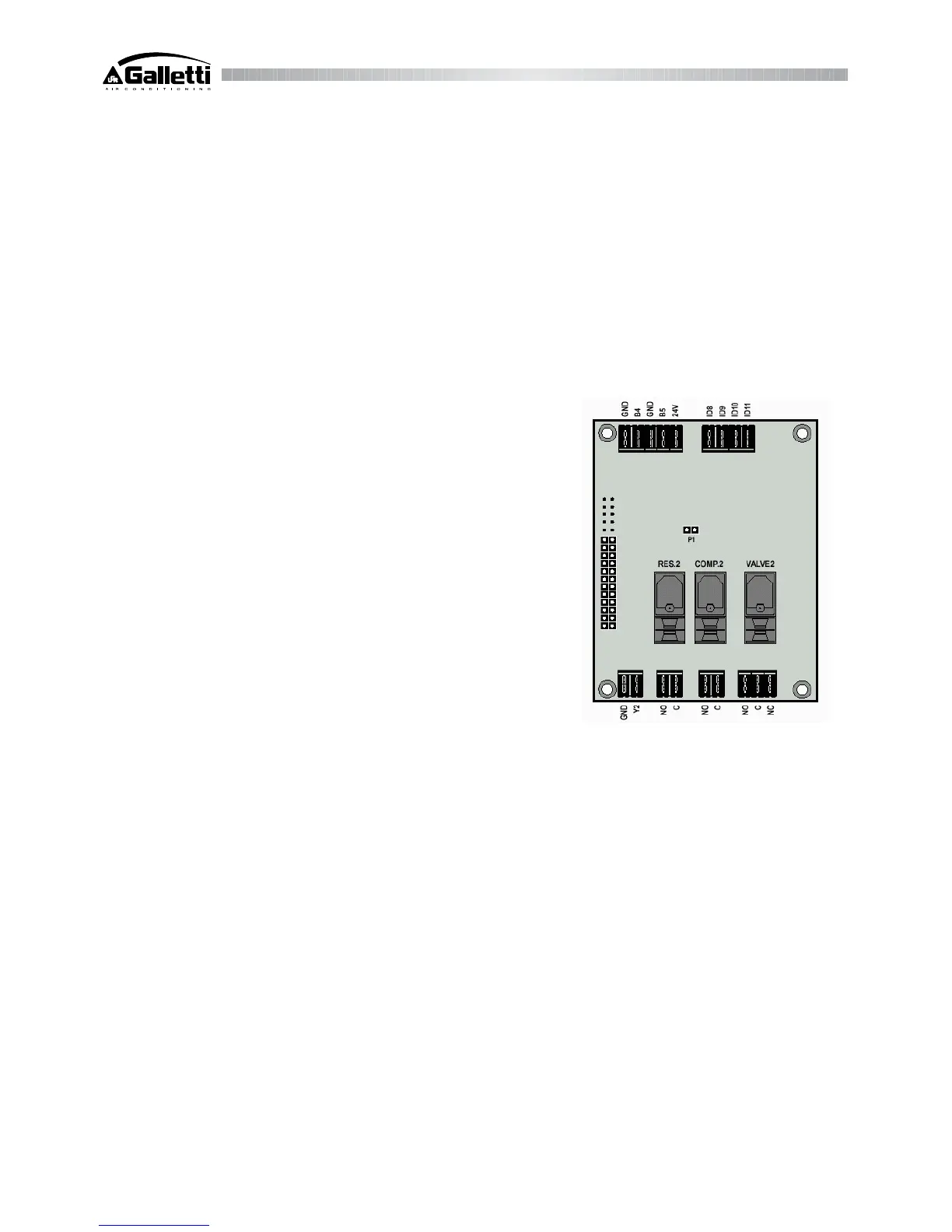
2.3 Second compressor board
It represents an expansion of the main board, which proves to be useful for the management of a second compressor unit; in
this case only the “COMP.2” terminal connection (used to manage the relative solenoid valve) must be effected.
The connection areas are the following (clockwise):
• analog inputs (B4 and B5) for the probes connection (relative to the second
circuit);
• 24V terminal (with D.C.) for the supply of any pressure probe;
• digital inputs (from ID8 to ID11) for safety connections (relative to the
second circuit);
• digital relay outputs to manage any controlled device;
• the Y2 GND analog output for the connection of the optional boards for the
management of condensation fans (ON/OFF regulation mode or with
continuous rotation speed variation);
• the flat cable for the connection to the single compressor main board;
• P1 pin-strip relative to the Y2 analog output (to be normally left open,
except in particular situations - see parameters F3 and F4).