RG66000889-REV.OO 18
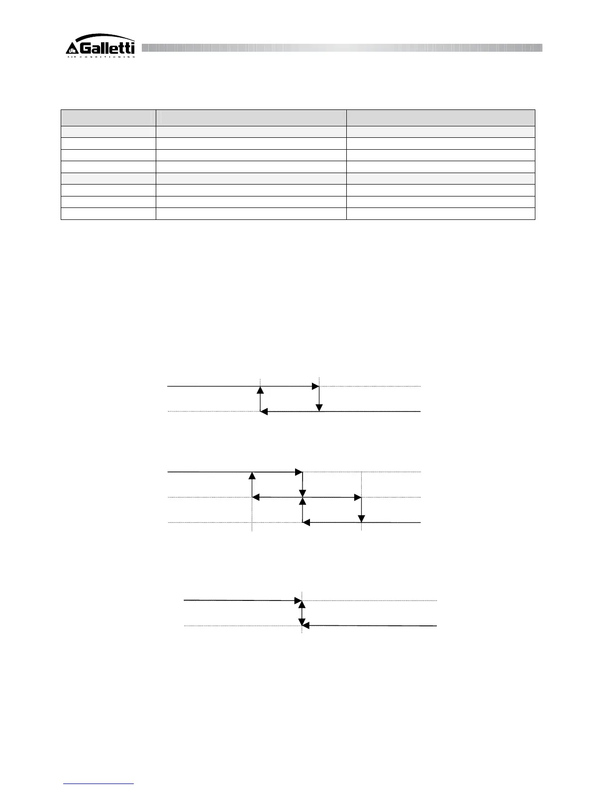
In capacity-controlled compressors, the functioning logic is as follows:
Request Compressor contactor Partialization solenoid valve
Start-up:
OFF disenergized disenergized
Capacity-controlled energized energized
Full load energized disenergized
OFF routine:
Full load energized disenergized
Capacity-controlled energized energized
OFF disenergized disenergized
Upon request of full load start-up, the capacity-controlled solenoid valve energizes; after 2 seconds the compressor relay will
be actuated. When the "c4" time-delay has passed (time-interval between compressor activation and relative capacity-
controlled routine) the solenoid valve will disenergize.
r3: Heating set-point
It allows to set the Heating set-point (reverse).
r4: Heating differential
It allows to set the Heating differential.
Heating functioning mode -1 compressor
Cooling functioning mode – 2 compressors or capacity-controlled routine
Cooling functioning mode ON/OFF probe
r5: Compressors rotation
This function makes it possible to activate the compressors so as to balance their operating hours. They are actuated
according to a "FIFO" (first in first out) logic, both at start-up and when the compressor turns off (the first to be turned on
will be the first to be turned OFF. The first to be turned OFF will be the first to be turned on).
r6: Water temperature @ evaporator output circuit no.1, B2
It displays the temperature at evaporator outlet in circuit no. 1 (B2).
Winter Set Point Winter Set Point + differential
Winter Set Point Winter Set Point + differential
Close contact
Compressor
Open contact