5
Mechanical Installation
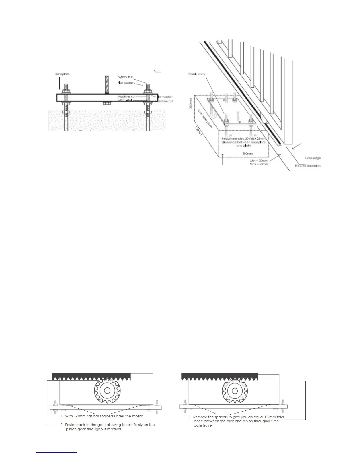
*Shown above is a guide for positioning and set up for the base plate in relation to the gate.
1. Check that the gate runs smoothly throughout its travel and does not bind anywhere.
2. IMPORTANT Ensure gate stops are fitted at the fully open and closed positions. These stops need
to be engineered and installed in such a way that they will be strong enough to stop the gate if the limit
switch fails to activate.
3. As an easy, quick set up, bolt the operator onto the base plate first, then sit the operator on top of the
base plate on the concrete, adjust the operator at a location where the pinion gear meshes fully onto the
rack and ensuring the pinion face is parallel with the gate rail. Now at this position, mark through the 4
x mounting holes on the base plate to show where to drill for the fixings.
4. Remove operator/baseplate.
5. Drill for the fixings.
6. Dynabolt mounting plate to concrete pad using 10mm x 100mm dynabolts.
7. If the anti-tamper bar is to be used, follow the steps below.
8. Or, position the operator/base plate back in positon, and bolt down to the concrete. Now you can positon
the operator in the best position to suit the gate rack by starting at one end, loosely hold a piece of rack
on top of the pinion, and gently against the gate rail, then slide the gate along. Take not of the best
position for the operator by sliding in or out to suit. Tighten the 2 x operator fixing bolts onto the base
plate.
9. Manually release the operator by unlocking the manual release lever with the supplied key and opening
the release door. Then start attaching rack to the gate frame ensuring that the rack meshes onto the
pinion gear with 1 – 2mm clearance.
(another suggestion for setting clearance on page 7)
10. Rack is normally tek screwed to gate rail. After fixing the rack for the full length of the gate, run the
gate back and check the rack meshes to the pinion gear without being too high or too low.
*Another method for achieving clearance between pinion and rack.
 Loading...