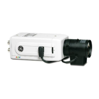
Installation Instructions
7
Note:
Figure 4 and Figure 5 show connections for the pins on the solder side of the lens plug.
NC (no
connection)
Red
(12 VAC
power)
Damping
coil (+)
Damping
coil (–)
Black
(ground)
White
(video)
Driving
coil (–)
Driving
coil (+)
Figure 4. Video-type auto iris lens leads
Figure 5. DC-type auto iris lens leads
• For auto iris lens with built-in EE amp, follow the connections in Figure 4. (Refer to the lens
instructions.)
• For auto iris lens without EE amp, follow the connections in Figure 5. (Refer to the lens
instructions.)
1.1 S
ETTING THE
DIP S
WITCH
Set the DIP switch for your camera situation (see Figure 6 and Table 1).
Table 1. DIP switch settings
ATW/AWB
Auto-tracking white balance / auto
white balance (if applicable)
BLC ON/OFF
Automatic backlight on or off
NAGC/SAGC
Automatic gain control normal (30
dB) or super (36 dB)
R = .45 / r = 1
Gamma equals .45 or 1
L-LOCK/INT
Line-lock or internal synchronisation
Figure 6. DIP switches for colour
cameras
Day/Night camera only:
AUTO/MAN
Switches between automatic and
manual mode
DAY/NIGHT
In manual mode, the camera is set
manually for day or night conditions