Installation
FireShield Technical Reference Manual 2.5
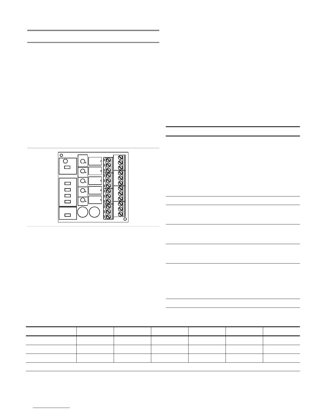
Installing the Remote Relay Module
The Remote Relay Module (FSRRM) provides five dry
contact relay outputs. The outputs can be wired as both
normally open and normally closed. The outputs can be set to
common or zone notifications (see the “Command options”
table below). Installing the appropriate jumper (JP3 - JP5)
configures the dry contact relay output options.
Five diagnostic LEDs provide visual indication of the status of
each relay. If the LED is lit, the relay is energized. If the LED
is off, the relay is de-energized. If configured for common
operation the trouble relay and the power relay will be
energized when the system is normal.
Note: You must run the Find Annunciators program option
after adding or removing a remote annunciator. The remote
annunciators will not operate properly until the panel detects
them. For more information see Chapter 3 “Programming.”
DISABLE
JP1
OUTPUTS
JP1 IN
MODULE TYPE
JP2
JP3
JP4
JP5
ZONE 11-15
ZONE 6-10
ZONE 1-5
COMMON
GROUP
IN
JP6
JP6
JP6
OUT
#1
#2
ACTIVE
OUT 1
OUT 2
OUT 3
OUT 4
OUT 5
DS4
DS5
DS2
DS3
DS1
TB1 TB2 TB3 TB4
Specifications
Max. per system
FS302 (three-zone): 4
FS502 (five-zone): 4
FS1004 (ten-zone): 6
Voltage range
Minimum: 21 Vdc
Maximum: 25 Vdc
Zoned operation current requirements
Standby: 8 mA
Alarm: 65 mA
Common operation current requirements
Standby: 30 mA
Alarm: 41 mA
Max. circuit capacitance: 0.03 µF
Max. circuit resistance: 13 ohms
Relay ratings: 30 Vdc @ 1 A (resistive load)
Wire size
Minimum: 18 AWG (0.75 sq mm)
Maximum: 12 AWG (2.5 sq mm)
Mounting: MFC-A cabinet or listed fire alarm enclosure
Operating environment
Temperature: 32 to 120 °F (0 to 49 °C)
Humidity: 93% RH, noncondensing
Jumper setup
Jumper Name Description
JP1 Disable
jumper
Disables all outputs. This allows the
installer to test the system while the
FSRRM is disabled. Removing the
jumper reactivates the FSRRM.
The disable jumper is supervised.
With the disable jumper in place, the
panel displays Trouble, Annunciator
Trouble, Disable, sounds the panel
buzzer, and de-energizes any
energized relay.
JP2 Reserved for future use.
JP3 Zone 6 -
10 jumper
Sets the five dry contacts to report
events on zones 6 through 10. See
“Command options” table. [1]
JP4 Zone 1- 5
jumper
Sets the five dry contacts to report
events on zones 1 through 5. See
“Command options” table. [1]
JP5
Common
jumper
Sets the five dry contacts to report
common events. See “Command
options” table. [1]
JP6 Group
jumper
The group jumper (JP6) allows two
FSRRMs to be connected to the
same panel and set to the same
output option. Install the jumper (JP6)
to only one of the two grouped
FSRRMs.
[1] Install only one zone jumper on J3 or J4 or J5.
Command options
Module type Jumper Output 1 Output 2 Output 3 Output 4 Output 5
Common JP5 Alarm Trouble [1] Supervisory Monitor Power [1]
Zone 1 - 5 JP4 Zone 1 Zone 2 Zone 3 Zone 4 Zone 5
Zone 6 - 10 JP3 Zone 6 Zone 7 Zone 8 Zone 9 Zone 10
[1] Under normal conditions the relay is energized (the internal LED is lit). Loss of power de-energizes the relay.