Installation
2.12 FireShield Technical Reference Manual
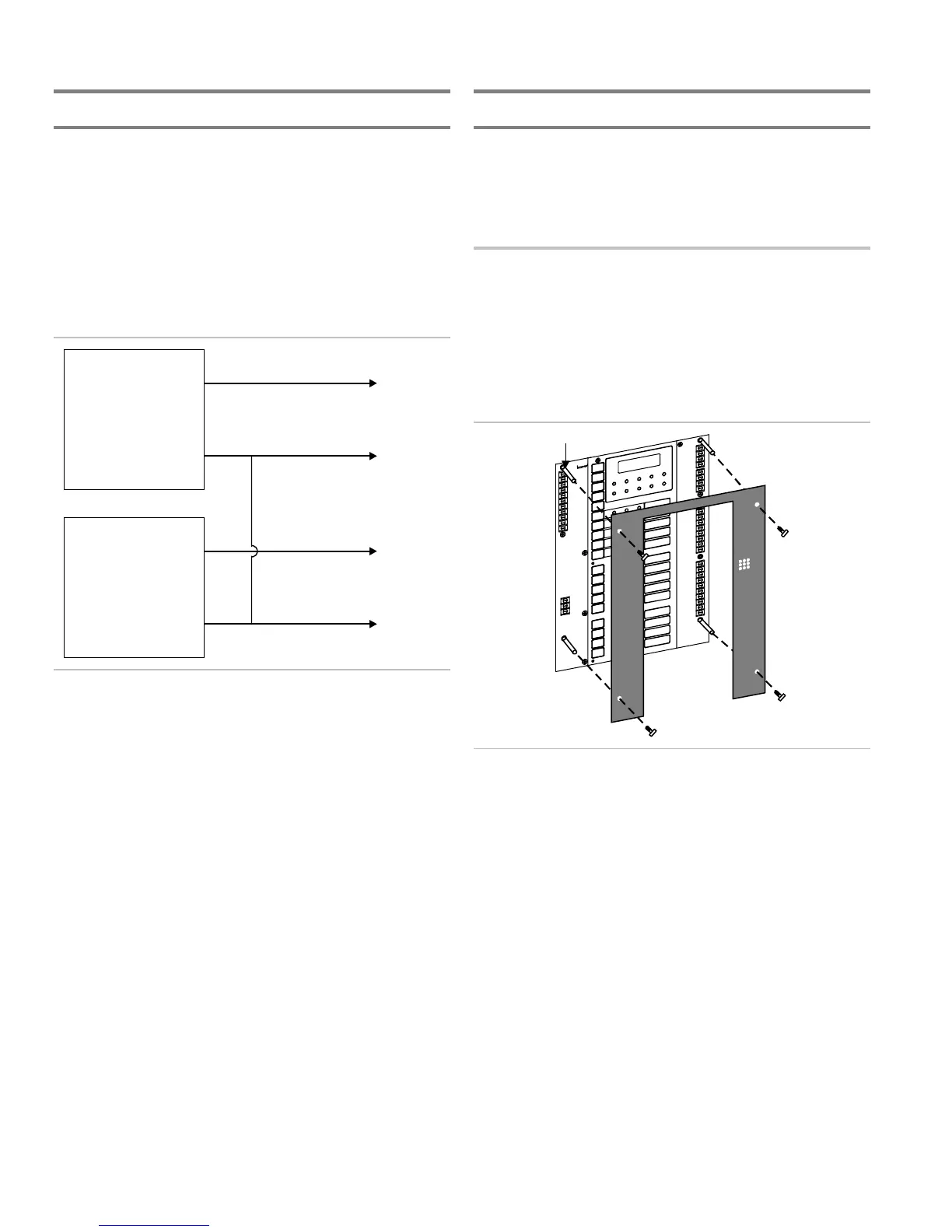
Connecting an auxiliary power supply
Aux power supplied by the panel cannot exceed 0.5 A. If more
than 0.5 A is required, you must use a compatible UL/ULC
listed fire alarm power supply.
When using an auxiliary power supply, you must connect the
-24 Vdc auxiliary terminal at the panel to the -24 Vdc output
terminal of the listed auxiliary power supply used to power
FireShield devices.
Note: For detailed wiring information, refer to the installation
instructions that came with the auxiliary power supply.
FireShield
FACP
Aux. Power
+
-
UL Listed
Aux. Power Source
+
-
To Devices
24 Vdc @ 0.5 A Max.
To Devices
Requiring Additional
Power
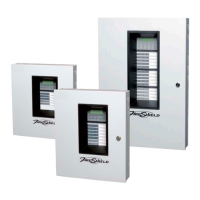
Installing the terminal shield
The terminal shields for the three, five, and ten zone panels
(model numbers ending in GC or GF) required for Canadian
installation, cover and protect the wire connections at the
terminal blocks.
To install the terminal shield:
1. Remove the four corner mounting screws from the circuit
board. Refer to the diagram below for location.
2. Mount the supplied standoffs to the four corner locations
where you removed the screws.
3. Mount the terminal shield to the standoffs using the
screws you removed in step 1. Refer to the diagram
below.
Standoff