NX-8V2-Control Panel
Installation Instructions
2
Module list
Table 3 shows the modules that are compatible with the NX-
8V2 system. Additional information and a catalog listing all
system components is available from GE Customer Support.
Note: The NX-8V2 control panel sends a trouble condition once each
hour if it senses that no devices have been enrolled. This report
shows expander trouble--device zero (0).
Control panel programming
Programming the control panel requires you to enter
program mode, select the module to program, program a
location, and then exit the location and program mode.
Enter program mode
To enter program mode, do the following:
1. Press ∗, 8. The five function LEDs (Stay, Chime, Exit,
Bypass, and Cancel) begin flashing.
2. Enter the go to program code (default is 9, 7, 1, 3). If the
go to program code entry is valid, the Service LED
flashes, and the five function LEDs illuminate. You are
now in program mode and can select the module to
program.
Select the module to program
Since all modules connected to the NX-8V2 are programmed
through the keypad, the module you are programming should
be the first entry. To select the module to program, enter 0, #.
The 0 is the module number of the control, and # is the entry
key. You can find other module entry numbers in the module
documentation.
Program a location
Once you enter the module number, the Armed LED illumi-
nates, indicating the keypad is waiting for you to enter a
programming location. To program a location, do the
following:
1. To access any location, enter the desired programming
location, followed by #. If the location is a valid location,
the Armed LED extinguishes, the Ready LED illuminates,
and the binary data for the first segment of the location
is shown by the Zone LEDs.
2. While entering new data, the Ready LED begins flashing
to indicate a data change in process.
3. Press ∗ to store the newly entered data. The keypad
advances to the next segment and displays its data.
Repeat this procedure until the last segment is reached.
4. To move to another location after exiting a location
(Armed LED illuminated):
• Press the Police key for the next sequential location.
• Press the Fire key for the previous location.
• Press the Medical key for the same location.
5. To review the data in a specific location, repeat the
above procedure, pressing ∗ but with no numeric data
entry. Each time you press ∗, the programming data of
the next segment displays.
Exit a location
To exit the current programming location, do the following:
1. Press the ∗ key. The Ready LED goes off and the Armed
LED goes on. You must press the ∗ key to save the data.
2. To exit before the last segment, press # (Armed LED illu-
minates).
You are now ready to enter another programming location. If
you attempt to program an invalid entry for a particular
segment, the keypad beeps three times indicating an error
and remains in that segment awaiting a valid entry.
Exit program mode
To exit program mode, do the following:
1. When you have completed all programming, press Exit
to leave the selected module.
2. If there is another module to be programmed, select it by
entering its address, followed by #. The procedure for
programming these devices is the same as for the
control panel, except the locations are for the module
selected.
3. If no additional modules are to be programmed, press
Exit again to leave program mode.
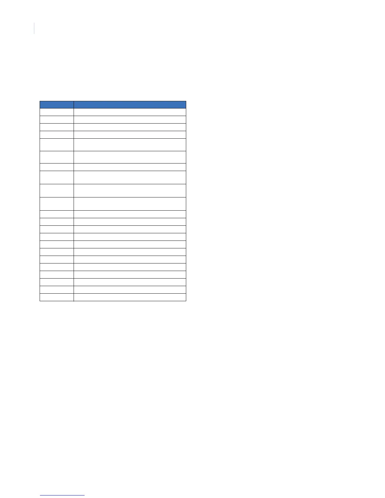
Table 3. Modules that can be added to the NX-8V2
Part Description
NX-108E 8-zone LED keypad
NX-116E 16-zone LED keypad
NX-124E 24-zone LED keypad
NX-148E Alphanumeric 48-zone LCD keypad
NX-148E-RF
b
Alphanumeric 48-zone LCD keypad with built-in 48-zone
wireless receiver
NX-200
a
a. These products have not been tested and approved by Un-
derwriters Laboratories, In.
Zone doubling kit (includes one hundred 3.74k and one
hundred 6.98k resistors)
NX-320E Smart power supply and bus extender
NX-408E
b
b. These wireless devices are UL listed only for residential ap-
plications.
8-zone wireless expansion module
(UL listed part #60-904)
NX-416E
b
16-zone wireless expansion module
(UL listed part #60-904)
NX-448E
b
48-zone wireless expansion module
(UL listed part #60-904)
NX-508E Eight-output module
NX-534E
a
Two-way listen-in module
NX-540E
a
Operator telephone interface module
NX-548E
b
48-zone wireless receiver
NX-591E-GSM
a
Cell interface
NX-1192E 192-zone LCD keypad
NX-1208E 8-zone LED keypad
NX-1248E 48-zone LCD keypad
NX-1308E 8-zone LED door design keypad
NX-1316E 16-zone LED door design keypad
NX-1324E 24-zone LED door design keypad
NX-1448E 48-zone fixed language icon keypad

 Loading...
