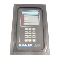
3 SETUP AND USE
g
GE Power Management
54
3$*( '(6&5,37,21
5
RELAY ALARM
LATCHCODE = XX
This setpoint allows the choice of output relay latch attributes. A latched output relay must be manually
reset. An unlatched relay will be automatically reset when the condition that caused the relay activation
goes away.
Note: Trip functions must always be manually reset regardless of the Latchcode value chosen
here.
This setpoint allows Alarm functions to be either manually or automatically resetable. The
Immediate O/L Alarm function will always be automatically reset regardless of the Latchcode.
latched = manual reset, unlatched = automatic reset
(see Table 3-6 for complete relay functions/configurations)
For the model 169 Plus:
Value Trip Alarm Aux. 1 Aux. 2
1 latched unlatched unlatched latched
2 or 3 latched latched unlatched latched
4 or 5 latched unlatched latched latched
6 or 7 latched latched latched latched
For the model 169:
Value Trip Alarm
1 or 4 or 5 latched unlatched
2 or 3 or 6 or 7 latched latched
Factory Value = 1
5
RELAY FAILSAFE
CODE = X
This code allows the choice of output relay fail-safe attributes. FS = fail-safe, NFS = non-fail-safe (see
Glossary). See Table 3-7 for complete relay functions/configurations.
For the model 169 Plus:
Value Trip Alarm Aux. 1 Aux. 2
1 FS NFS NFS FS (see Figure 2-5)
2 NFS FS NFS FS
3 FSFSNFSFS
4NFSNFSFSFS
5 FS NFS FS FS
6 NFS FS FS FS
7 FSFSFSFS
8 NFS NFS NFS FS
For the model 169:
Value Trip Alarm
1 or 5 FS NFS (see Figure 2-5)
2 or 6 NFS FS
3 or 7 FS FS
4 or 8 NFS NFS
Factory Value = 1
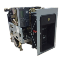
Note: Due to the hardware configuration of the 169/169 Plus drawout relay this code cannot be
changed on any drawout models without corresponding hardware change.