installation instructions
m CONNECTTHETUBINGTOTHE
REFRIGERATOR(CONT.)
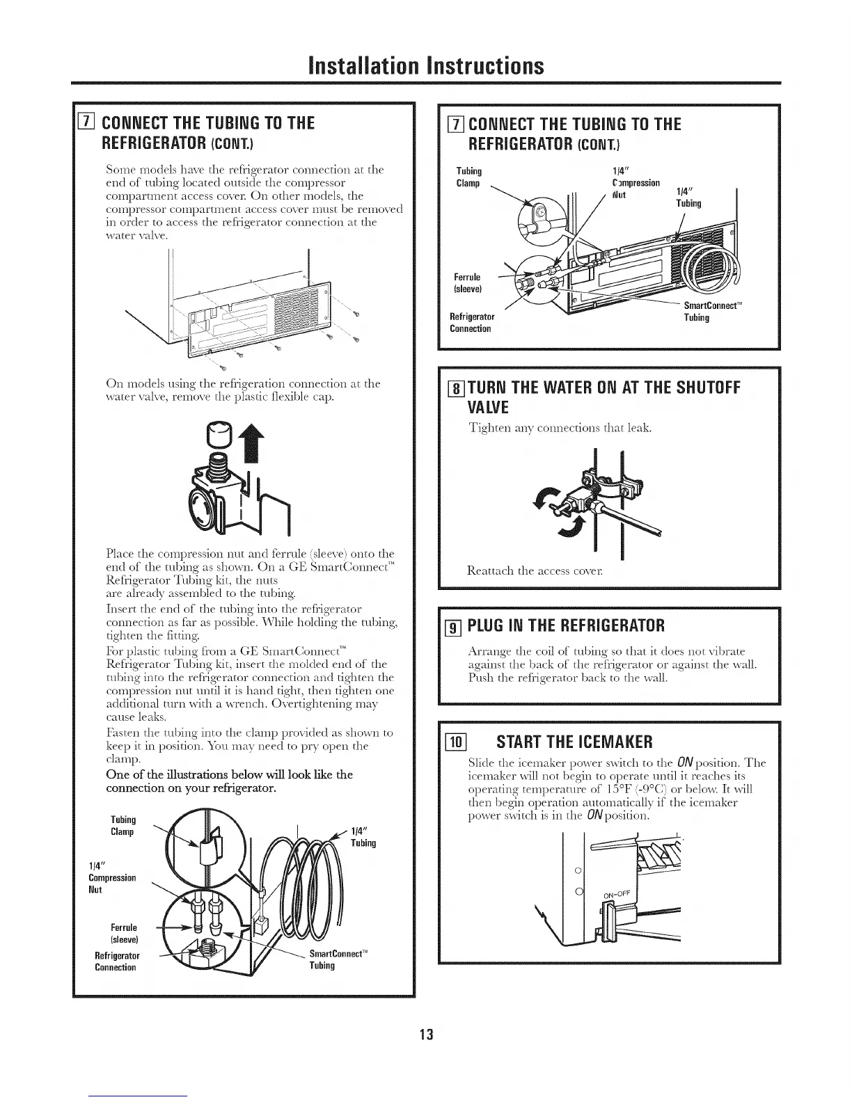
Some models have the refrigerator co:mection at the
end of robing located outside the compressor
compartment access cover. On other models, the
compressor coillpartillellt access cover i1]ust be removed
in order to access the refrigerator com:ection at the
water valve.
On models using the refrigerauon com:ection at the
water valve, remove the plastic flexible cap.
©
Place the compression nut and ferrule (sleeve) onto the
end of the robing as shown. On a GE SmartCom:ect _'
Refrigerator Tubing kit, the m:ts
are alrea@ asse:nbled to the robing.
Insert the end of the robing into the refrigerator
connection as far as possible. While holding the robing,
tighten the fitting.
For plastic tubing from a GE SmartConnect"
Refrigerator Tubing kit, insert the molded end of the
tubing into the refrigerator connection and tighten the
compression nut until it is hand tight, then tighten one
additional turn with a wrench. Overtightening may
cause leaks.
Fasten the tubing into the clamp provided as shown to
keep it in position. You may need to pry open the
clamp.
One of the illustrations below will look like the
connection on your refrigerator.
Tubing
Clamp
1/4"
Compression
Nut
1/4"
Tubing
Ferrule
(sleeve)
BeMgerator SmartConnecf_'
Cannection Tubing
J-_CONNECTTHE TUBING TOTHE
REFRIGERATOR(CONT.)
Tubing 1/4"
Clamp CJmpression
_ut
Ferrule
(sleeve)
Refrigerator
Cannection
J-_TURN THE WATERON AT THE SHUTOFF
VALVE
Tighten anycom:ections that leak.
Reattach the access cover.
PLUG INTHE REFRIGERATOR
Arrange the coil of tubing so that it does not vibrate
against the back of the refrigerator or against the wall.
Push the refrigerator back to the wall.
STARTTHE ICElVlAKER
Slide the icemaker power switch to the ONposition. The
icelnaker will not begin to operate until it reaches its
operating telnperature of 15°F (-9°C) or belo_xcIt will
then begin operation autolnatically if the icelnaker
power switch is in the 0Nposition.
13

 Loading...