EasyManua.ls Logo

GE 27" DROP-IN RANGE User Manual

GE 27" DROP-IN RANGE
4 pages
To Next Page IconTo Next Page
Page #1 background imageLoading...
Page #1 background image
_'em_ve h_use _se o_' epe_ c_rc_t
_'eak_r before beginning
A_T_O_AL _AT_R_ALS
This range is designed to hang from the countertop. It
does not rest on the floor.
If countertop is less than 1 1/2" thick, reinforcing braces
must be installed under the countertop, on each side.
See Figure 1.
Large blade screwdriver
Channel lock pliers
oPhillips head screwdriver
Hand or Electric Drill
,, 1/8" Drill Bit
oHand or Saber Saw
Tape Measure
Straight Edge
oPencil
NOT_: Remove a_ protective p_ast_¢ coating
_rom doo_" _'rame be_'o_'e _nstaHat_on.
30" MIN.
TRIM SECTION FOR
COU
POST FORMED OR
RAISED FRONT EDGE
21 3/4" CABINET FACE
TO REAR OF CUT-OUr
28 7/16"
MOULDING MAY BE FITTED TO
THE OVEN TRIM FOR A MORE
CUSTOM APPEARANCE
_IF NEEDED, BUILD UP SIDES OF CUTOUT TO A MIN. OF
1 1/2" TOTAL THICKNESS (FULL DEPTH OF CUTOUT).
28 1/2"
MIN.
JUNCTION BOX LOCATION
BOX MUST NOT EXTEND MORE THAN
3" OFF THE PLANE OF THE WALL)
SEE NEXT PAGE
Fig. 1
Pub. No. 31-10417
229C4053Pt 21
Question and Answer IconNeed help?

Do you have a question about the GE 27" DROP-IN RANGE and is the answer not in the manual?

GE 27" DROP-IN RANGE Specifications

General IconGeneral
BrandGE
Fuel TypeElectric
Number of Burners4
Self-CleaningYes
Power SourceElectric
TypeDrop-In
Size/Width27 inches

Summary

Location and Spacing Requirements

General Location Guidelines

Position range near work surface, ensuring adequate clearance and lighting for safe operation.

Cabinet and Wall Clearance

Maintain minimum clearances from cabinets, walls, and countertop edges for safety and ventilation.

Junction Box Placement

Locate junction box at rear of cutout, ensuring proper dimensions and slack for servicing.

Electrical Requirements and Connection

Voltage and Circuit Needs

Appliance requires specific voltage, frequency, and a grounded branch circuit protected by breaker or fuse.

Wiring Recommendations

Recommend using a qualified electrician for wiring and hookup, and identifying the main disconnect.

Conductor Requirements

Details on four-conductor and three-conductor branch circuit connections for new and existing construction.

Electrical Connection Steps

Steps for de-energizing the circuit and connecting the flexible conduit to the junction box.

Range Installation Procedure

Prepare for Installation

Ensure branch circuit is de-energized before starting installation.

Remove Oven Door

Open door to broil stop position and lift off hinges for easier handling.

Position Range in Opening

Lift cooktop, attach trim, and secure range to countertop using provided screws.

Replace Oven Door

Align door slots with hinge arms and slide down to secure.

Optional Backsplash Kit

Backsplash Kit Purchase

Details on purchasing and ordering specific GE Backsplash Kits by color.
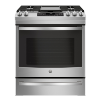
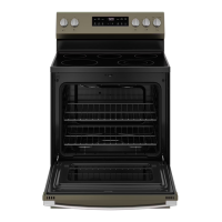
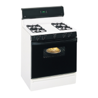
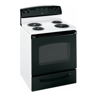
Related product manuals