12
4) Ground the 75 OHM Grounding Block:
Connect a #8 aluminum or #10 grounding wire to a
screw terminal provided on the 75 ohm grounding block.
Connect the other end of the wire to an acceptable
building ground location.
Examples of acceptable building grounding locations are:
• The building or structure grounding electrode system
as covered in 250.50 in the NEC.
• Grounded interior metal water piping system, within
5ft. from its point of entrance to the building.
• Grounded nonflexible metallic power service raceway.
• Service equipment enclosure, the grounding electrode
conductor or the grounding electrode conductor metal
enclosure of the power service.
• An 8-foot grounding rod driven into the ground can be
used as long as it is connected to the central building
ground by a #6 or heavier bonding wire.
Be sure to double check all your connections after your
installation is complete. Ensure there are good electrical
connections of your grounding wires and coax cables. See
Fig. 2 below for an example of a properly grounded antenna
installation.
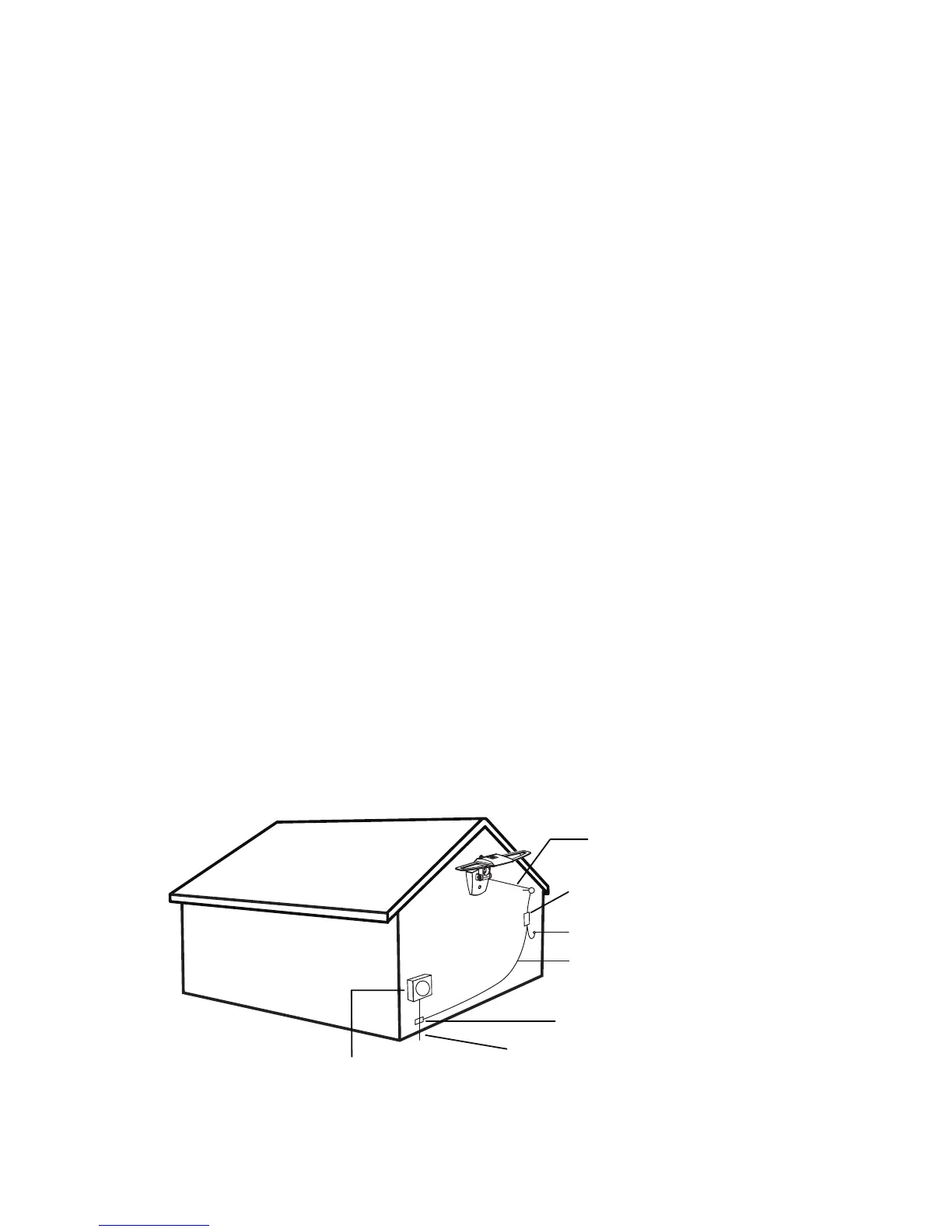
Example of Antenna Grounding
as per NEC - National Electrical Code
ELECTIC SERVICE METER PANEL
POWER SERVICE GROUNDING ELECTRODE
SYSTEM (NEC ART 250. PART H)
GROUNDING CONDUCTOR
(NEC SECTION 810-21 )
GROUND CLAMP
75 OHM GROUNDING BLOCK
(NEC SECTION 810-20)
ANTENNA COAX
RAIN DRIP LOOP FOR THE COAX TO TV
Fig. 2
If you are unsure how to properly ground your antenna
installation, contact a professional installer in your area.
Fig. 2