CHAPTER 4: SETPOINTS SYSTEM
845 TRANSFORMER PROTECTION SYSTEM – INSTRUCTION MANUAL 4–87
Differential and Restraint Current Calculations
Two Winding Transformer
Differential currents are calculated as follows:
Id
A
= I
A
C
[w1] + I
A
C
[w2]
Id
B
= I
B
C
[w1] + I
B
C
[w2]
Id
C
= I
C
C
[w1] + I
C
C
[w2]
Restraint currents are calculated as follows:
Ir
A
= max {|I
A
C
[w1]| , |I
A
C
[w2]|}
Ir
B
= max {|I
B
C
[w1]| , |I
B
C
[w2]|}
Ir
C
= max {|I
C
C
[w1]| , |I
C
C
[w2]|}
where Id
A
, Id
B
and Id
C
are the phase differential currents, and Ir
A
, Ir
B
, and Ir
C
are the phase
restraint currents.
Three-Winding Transformer
Differential currents are calculated as follows:
Id
A
= I
A
C
[w1] + I
A
C
[w2] + I
A
C
[w3]
Id
B
= I
B
C
[w1] + I
B
C
[w2] + I
B
C
[w3]
Id
C
= I
C
C
[w1] + I
C
C
[w2] + I
C
C
[w3]
Restraint currents are calculated as follows:
Ir
A
= max {|I
A
C
[w1]| , |I
A
C
[w2]| , |I
A
C
[w3]|}
Ir
B
= max {|I
B
C
[w1]| , |I
B
C
[w2]| , |I
B
C
[w3]|}
Ir
C
= max {|I
C
C
[w1]| , |I
C
C
[w2]| , |I
C
C
[w3]|}
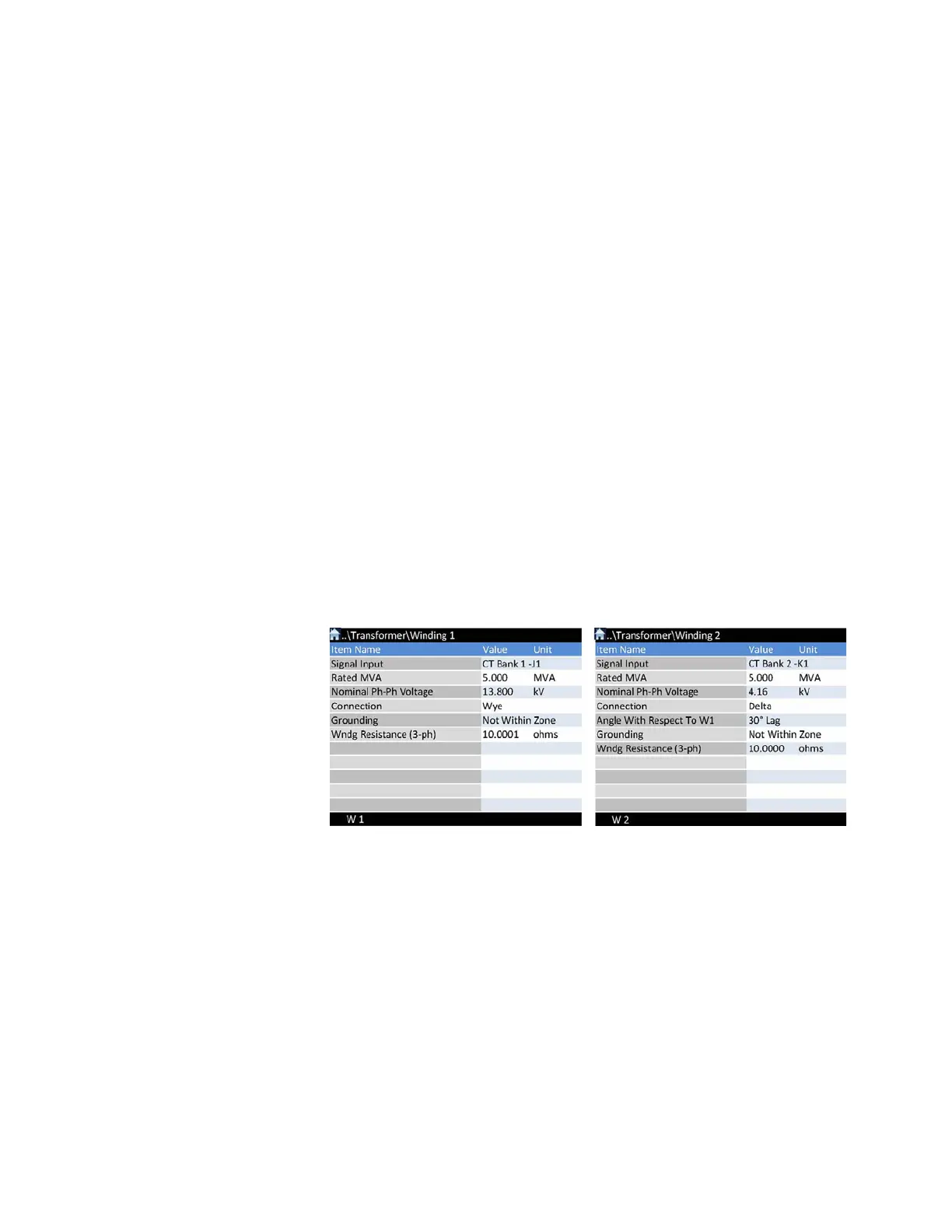
EXAMPLE
Consider a typical Wye/Delta power transformer with the following data:
• Winding 1: CT Bank 1 – J1 = 500/5 CT ratio
• Winding 2: CT Bank 2 – K1 = 1500/5 CT ratio
• Transformer is 50% loaded
Magnitude Compensation
Based on 50% loading the winding currents are calculated as follows:
Winding 1 load current: I
load
(W1) = 2.5MVA/(3 * 13.8kV) = 104.5 Amps
Winding 2 load current: I
load
(W2) = 2.5MVA/(3 * 4.16kV) = 347 Amps
Since Winding 1 is always magnitude compensation reference, the currents from winding
1 , are scaled only to be presented in times Winding 1 CT.
M
W1
= 1 , - magnitude compensation factor for winding 1 - REFERENCE
Winding 1 currents = (M
W1
*I
load
(W
1
))/CT
W1
= 104.5/500 = 0.209 x CT
W1