4–88 845 TRANSFORMER PROTECTION SYSTEM – INSTRUCTION MANUAL
SYSTEM CHAPTER 4: SETPOINTS
Magnitude compensation for winding 2 currents:
M
W2
= (CT
W2
.V
W2
)/ (CT
W1
.V
W1
) = (1500*4.16)/(500*13.8) = 0.9043, -magnitude comp.
factor for Winding 2 currents
Winding 2 currents = (M
W2
* I
load
(W
2
))/CT
W2
= (0.9043*347)/1500 = 0.209 x CT
W2
To check that the measured currents from both windings will sum-up to zero after
applying magnitude compensation, one can perform the following simple calculations:
Phase Shift Compensation
From the transformer example, the phase reference winding is winding 2 (i.e.,w
f
= 2). The
phase compensation angle for each winding is then calculated as follows (Rotation =
“ABC”):
φ
comp
[1] = -30°– 0° = -30° = 30° lag
φ
comp
[2] = -30° – (–30°) = 0°
The non-reference Wye winding will be rotated by -30° degrees to be in-phase and match
the currents from the Delta winding.
Per figure: Two-winding transformer connections for phase compensation angle of 30 lag,
the relay will use the following phase and zero-sequence compensation equations:
Winding 1 (Wye – grounded neutral):
I
A
p
[w]= (1/3)I
A
[w] - (1/3)I
C
[w]
I
B
p
[w]= (1/3)I
B
[w] - (1/3)I
A
[w]
I
C
p
[w]= (1/3)I
C
[w] - (1/3)I
B
[w]
Winding 2 (Delta):
I
A
p
[w] = I
A
[w]
I
B
p
[w] = I
B
[w]
I
C
p
[w]= I
C
[w]
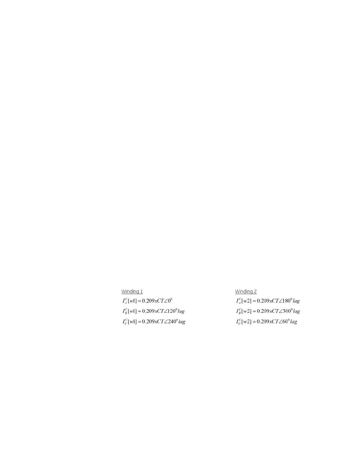
The complete compensated winding 1 and winding 2 currents would be as follows:
The differential and restraint currents would be as follows:
Differential currents:
Id
A
= 0 x CT
Id
B
= 0 x CT
Id
C
= 0 x CT
Restraint currents:
Ir
A
= 0.209 x CT
Ir
B
= 0.209 x CT
Ir
C
= 0.209 x CT