EasyManua.ls Logo

GE AK-1-15 Series - Page 27

GE AK-1-15 Series
31 pages
To Next Page IconTo Next Page
To Previous Page IconTo Previous Page
Loading...
'
tUI
'
J
PAGE
16
w
w
«
j
.
-
r
iJ
.
.
*
"
»
i
^
W
-
.
Y
Air
Circuit
Breakers
Type
AK
~
:
i
~
J
.
5
and
AK
-
i
>
25
GEH
-
1607
j
i
ORAWOUT
BREAKER
-
v
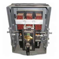
The
drawout
type
circuit
breaker
(
a
»
o
Fig
*
28
)
V
insists
of
a
circuit
breaker
mounted
in
.
a
drawout
carriage
.
The
drawout
carriage
is
equipped
with
guides
,
a
racking
handle
and
raectoamsxiw
and
an
interlock
arrangement
which
prmuto
toe
fnmartion
or
withdrawal
of
the
breaker
while
in
the
clawed
position
.
Also
included
are
the
primary
and
second
-
ary
disconnect
CICYIOCB
*
Tlda
type
of
br
-
eoter
to
used
with
weatherproof
,
encloeureu
and
switchgear
equipments
ouch
as
load
ccuter
oub
-
atationa
*
Their
use
m
toe
better
case
to
covered
more
completely
in
Switchgear
Instruction
GEtt
-
iCSO
,
j
}
Inserting
Breaker
To
Install
the
drawout
breaker
in
the
enclosing
case
,
proceed
as
follows
;
1
,
Raise
the
breaker
wo
'
that
the
guides
(
5
)
in
the
supporting
channel
(
4
)
,
Fig
,
24
*
Zt
Raise
the
radk
-
but
handle
,
and
push
too
carriage
back
until
then
rack
-
out
pins
on
the
handle
sockets
rest
against
the
back
edge
of
the
housing
rack
-
out
cams
(
8
)
,
Fig
,
£
4
,
3
,
Push
downward
on
the
ruok
-
out
'
handle
,
thus
forcing
the
racif
-
out
pins
upward
in
the
housing
cam
and
the
primary
disconnecting
devices
into
contact
*
4
*
Poll
the
rack
-
out
handle
downward
so
that
locking
pin
(
4
)
,
,
Fig
.
&
S
,
Is
in
the
vortto
^
l
section
of
the
oAm
slot
(
6
)
,
Fig
.
25
*
The
breaker
trip
cam
,
guided
by
the
rack
-
out
handle
,
wow
permits
the
breaker
to
be
closed
.
rest
>
*
*
*
>
m
&
w
a
NUIP
^
«
VI
u
.
6
,
ttmdlc
Socket
7
*
keittk
-
Out
Handle
8
.
Cm
Slot
9
.
Trifi
Ofti
1
,
Second
2
.
LftVftr
3
,
kack
-
out
iPxn
4
.
Lodcinfi
;
Tin
3
»
QUido
1
)
1
a
connect
Ihtwriock
Withdrawal
To
withdraw
the
breaker
from
the
enclosing
case
,
proceed
as
follows
:
!
.
1
,
Trip
the
breaker
by
pushing
the
manual
trip
button
,
-
If
the
breaker
to
not
open
the
positive
interlock
lever
(
2
)
will
prevent
locking
pin
(
4
)
from
moyiiig
upward
and
will
thereby
prevent
withdrawal
of
the
breaker
.
Each
dtoeonnoct
coxuBlals
of
four
contactfingera
2
.
Lift
the
rack
-
out
handle
vertically
.
This
(
3
)
secured
UrOach
breaker
stud
(
7
)
by
screw
.
(
1
)
operation
unlock
*
the
breaker
carriage
and
and
retainers
(
0
and
8
)
.
A
pair
of
springe
(
2
)
exert
raison
the
breaker
trip
cam
,
preventing
pressure
on
the
contact
fingers
when
engaging
the
closing
of
the
toeakaiv
;
,
stationary
studs
(
4
)
.
Stop
(
5
)
and
rotahmrs
(
6
and
8
)
3
*
Pull
toe
rack
-
out
handle
forward
in
&
olr
~
seiwe
to
maintain
the
proper
alignment
of
toe
culAr
motion
until
the
primary
dtaeoiinec
!
ting
fingers
whew
engaging
the
breaker
studs
,
devices
are
disengaged
.
The
breaker
can
now
be
removed
from
the
enclosing
case
by
pulling
toward
on
toe
ra
<
!
k
*
-
out
handle
*
Fig
.
27
!
UluBtoatos
the
construction
of
toe
'
V
.
/
;
:
primary
dtocomoct
for
too
AK
-
l
-
SSS
breaker
.
Note
NO
IE
:
lo
test
and
!
inspect
toe
drawout
breaker
that
tho
on
centric
bushing
in
too
pente
of
too
t
.
.
is
not
in
the
enclosing
case
,
it
to
necessary
assembly
1
st
positioned
«
0
tout
its
thinnest
wall
too
^
am
ilottfif
Fig
ll
>
^
86
,
)
e
at
attorn
'
of
section
.
is
from
too
breaker
and
toward
the
for
toe
AK
~
b
'
h
Prwoui
Breaker
2
$
'
J
r
when
It
The
assembly
of
the
disconnect
15
is
the
same
except
the
central
bushing
Is
not
eccentric
and
retainer
(
0
)
1
»
of
a
different
design
.
DISCONNECTS
PRIMARY
DISCONNECTS
,
The
primary
disconnects
{
me
FIK
,
Vi
)
Attached
to
the
circuit
bi
-
oakor
studs
oh
toe
aide
of
die
breaker
.
!
A
NOTE
;
Al
'
0
rear
;
For
instructions
on
mounting
the
breaker
by
imma
of
dtoconnecta
,
nee
"
Dead
Front
Breakers
under
Jxuitalkiion
.
27
\
:
-
1
!
Courtesy of NationalSwitchgear.com

Related product manuals