GEK--7302
Installation and Operation
of
•rype
AK
Power Circuit
Breakers
3. Rotate the
two
track
lock links,
and
pull the right
track
all the
way
forward.
4. Using a lifting device and the spreader
provided for these
breakers,
raise
the
breaker and position
it
so that the
mounting pins on the side
of
the breaker
line
up
with the slots in
the
track
and
are
about 2 inches above the track.
G,
Pull the left
track
out and lower the
breaker so that the mounting pins
engage the slots in the
tracks.
6,
Engage the racking handle. This
is
done
by
pushing the trip button in the breaker
escutcheon, sliding the cover below
it
to the right
1
and
inserting the handle
on
the jacksnaft.
7. Turn the handle counterclockwise as
far
as
it
will
go,
(if
it
will move
in
that direction) and remove the handle,
B.
Push the breaker
in
against the
track
stops,
and
lock the
track
links.
9. Close the compartment door, Again
engage the handle
·as
in step
6,
and
rotate the handle clockwise
as
far
as
it
will go. Towards the end a high
force requirement will be fell
as
the
disconnect fingers
on
the
l;>reakex·
en
..
gage the stationary studs. A couple
of
turns
later,
and tho stop will be en
..
countered. The position indicator will
now
show
"CONN.
11
Breaker
Removal AK-2A/1!;
1.
Trip the
breaker.
".
2.
Move
the
breaker
and inner housing
to
the fully withdrawn position.
{See
Breaker
Insertion, Steps 1, 2 and 3).
3, Rotate
the
two
track
lock
links
and
pUll
the
breaker
out to
the
limit
of
the
track
travel. Attach lifting device
and lift breaker
up
and
away
from
compartment until
primary
disconnects
clear
the compartment.
4.
Move
the inner housing
to
the connected
position
by
pushing the
tracks
back
against the
track
stops and then follow
Steps 7
and
8 under
Breaker
Insertion.
The inner housing
is
now
in the con
..
nected position and the
breaker
is free
from
its
compartment.
Break~emova!
AK~4A/5~
1. Trip the breaker.
2. Engage the handle and rotate ltcounter-
clockwise.
If
the
breaker
closing spring
is
fully charged,
it
Will
be discharged
automatically a couple
of
turns before
the end
of
the action.
3. Open the door, unlock the
track
locks,
and pull the breaker all the
way
forward.
'Jlhe
breake:i;•
may
now
be lifted from
the tracks.
NOTE: The Installation of
AK-2/3-500/75$/
IOOS/ AKF2C/2D and
breakers
equipped with
the quick-closing mechanism
is
the same as
the other breakers described in this book.
The only difference occurs with drawout
breakers.
The compartmentsthathousethe
quiok
...
close
breakers
will be equipped with
an interlock that prevents the manual
dis~
charging
of
the closing springs while the
breaker
is
in the racked in (connected
position). This interlock,
when
requestedJ
will
be
provided with both
AKD
and
AKDe
equipment that require quick close
breakers
CONNECT!QN~
All electri'cal connections should be
made to assure
good
conductivity. Mating
surfaces should be parallel and firmly
bolted
or
clamped together. Contact
surN
faces should be clean and have a smooth
finish. The bus
or
cable connecting to the
breaker should have adequate
ourrent-
cal·rying capacity to prevent · excessive
heating. Control circuit connections should
be made according
to
the wiring diagram
Which
applies to each breaker
S.i>ecific·auy.
Depending
on
the breaker type, those con-
nections
are
made either to a terminal
board
on
the breaker
or
to-
the stationary
parts
of
the secondary disconnects.
INDIVIDUALLY llNCLOSED
AND
STATIONARY BREAKERS
The custo1ners external connections
foX'
operation
of
breaker control components
and accessories
are
shown
in
Fig, 1.
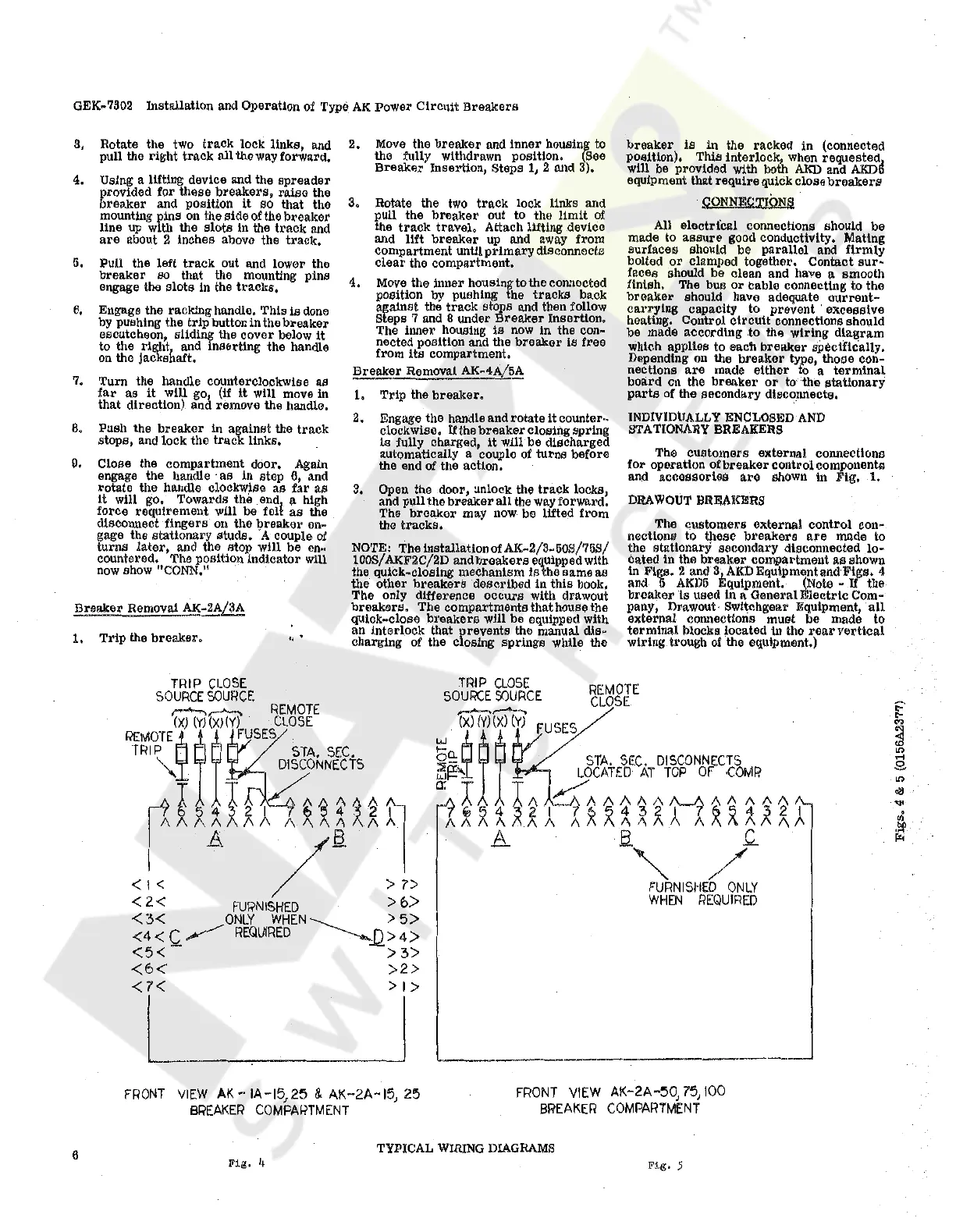
DRAWOUT
BREAKERS
The customers external control con
..
nectiona
tO
these b1•eakers
are
made to
the statlonarY secondary disconnected lo-
cated in the breaker compartment
as
shown
in Figs. 2 and 3i.AKDEqulpmentandFlgs, 4
and
l>
AKD5
"'quipment. (Note -
If
the
breaker ls \tsed in a General Electric Com-
pany, Drawout· Switchgear Equipment,
all
external connections must be made to
terminal blocks located in the
rear
vertical
wiring trough
of
the equipment.)
TRIP
CLOSE
SOURCE SOURCE
REMOTE
CLOSE
____
,..........._~
w
(2X)
~(Y)(~X)
(Y)
FUSES
....
o~
STA.
SEC.
DISCONNECTS
~f"'-
LOCATED
AT
TOP
OF
·COMP.
A
Ix
~
l
~
ff~
~ ~
~ ~
t~
~ ~
*
~
~
A
A B
.c_
""
/
FURNISflED
ONLY
WHEN
REQUIRED
FRONT
VIEW
AK--IA-15,25
& AK-2A-15, 25
BREAKER
COMPARTMENT
FRONT
VIEW
AK-2A-50,
75,
100
BREAKER
COMPARTMENT
6
Fig,
4
TYPICAL WIRING DIAGRAMS
Fig,
5
Courtesy of NationalSwitchgear.com

 Loading...


