GEI-861518
9. Close the compartment door.
Insert
the racking handle
(part
no. 5688731G1) through
the opening at
the
upper right
of the door and
onto the
jackscrew
shaft. By rotating the
handle
clockwise, move the
breaker
through the TEST
posi-
tion into
the CONNECTED
position;
the latter is indicated
when the
jackscrew
comes to a solid stop. All three
positions
-
DISCONNECTED,
TEST and CONNECTED
-
are
in-
dexed
on
the right
side of the breaker escutcheon.
Breaker Removal
(Code
B)
1. With the
door closed and latched. trio the breaker.
2.
Insert
the racking
handle
and rotate
it
counterclockwise
untilthe
breakertravels
from
CONNECTED
through TEST
to
the DISCONNECTED
position,
as indicated bythe
jackscrew
coming to a
solid stop.
This
operation should be
performed
with the door
closed.
3. Open the door. On
electrically operated breakers, de-
press
the
Spring
Discharge lever
to discharge
the
breaker's
closing springs. While holding this lever depressed,
pull
the
breaker all the way
out
to its WITHDRAWN
position.
On
manually
operated breakers this release
lever is la-
beled
"Push
to Withdraw".
See
Par.
8 on
previous
page.
4. Before
proceeding
with subsequent
operations to re-
move
the
breaker
from
the compartment, visually
check the
breaker's spring charge and close indicators to verify
that the
breaker
is
open and the springs
are discharged.
5.
Remove the
two-g/e inch hex head screws which fasten
the breaker to the
compartment tray.
6.
Attach the lifting
device
to the
cutout
notches
in
the top
wraparound frame
of
the
breaker, using care
to
prevent
dam-
age
to the
wiring.
7. Lift the
breaker
approximately
one-half
inch off the
dowel
pins.
Push the
tray back
into the
compartment.
8.
Swing
the
breaker forward until the
primary
discon-
nects
clear the comoartment. Lower the breaker onto a flat
surface
free
of
protrusions
that could damage the breaker's
internal
oarts.
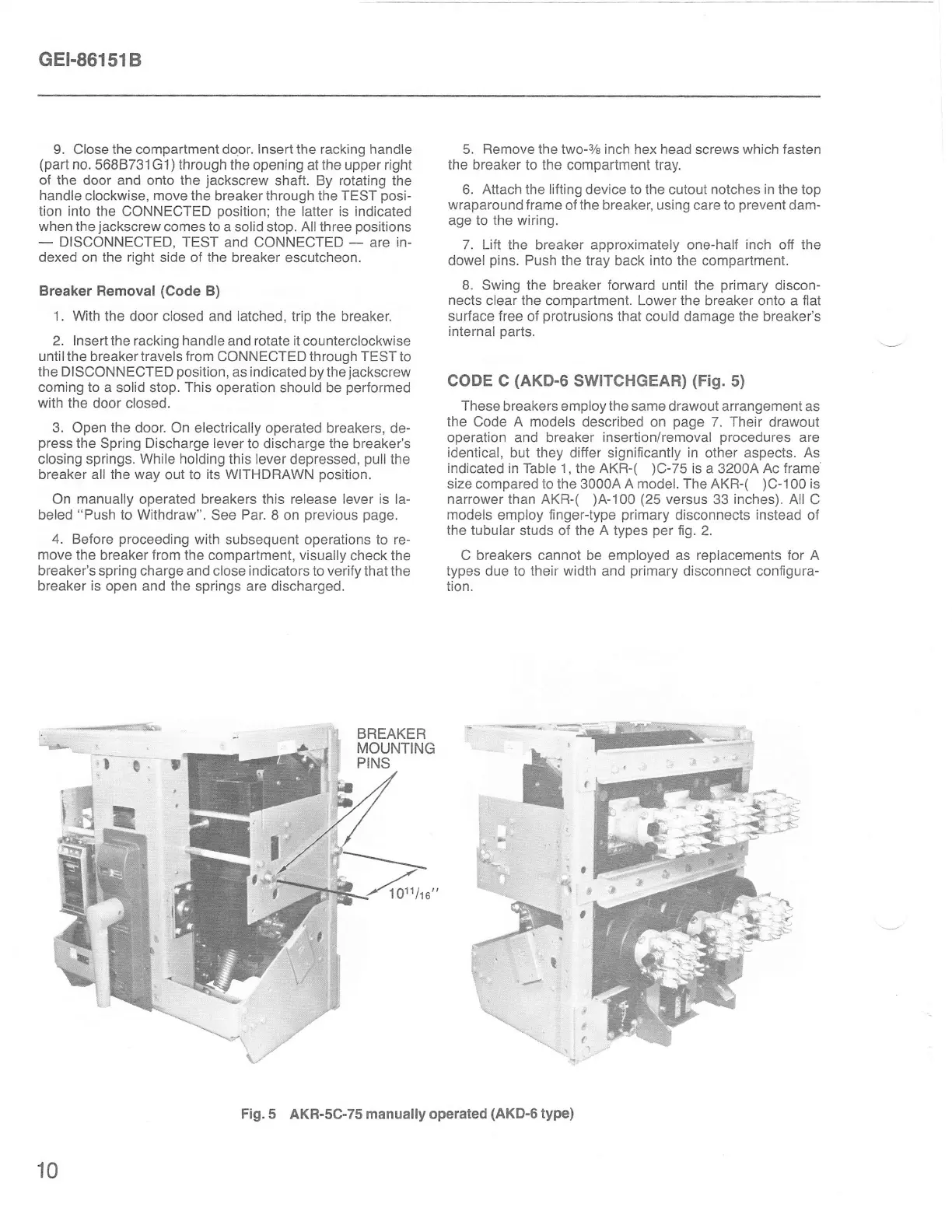
CODE c
(AKD-6
SWITCHGEAR)
(Fig.
s)
These
breakers
employ the same
drawout arrangement as
the Code A models
described on
page
7. Their drawout
operation and breaker
insertion/removal
procedures
are
identical,
but
they
differ significantly
in
other aspects.
As
indicated
in Table
1,
the AKR-(
)C-75
is a 32004 Ac
frame
size compared
to the 3000A
A model. The
AKR-(
)C-100
is
narrower than AKR-(
)A-100
(25
versus 33 inches).
All C
models
employ
finger-type
primary
disconnects
instead
of
the
tubular
studs of
the A types
per
fig.
2.
C breakers cannot be employed as
replacements for
A
types
due
to their width
and
primary
disconnect
configura-
tion.
"'se!
._
r ,
;t-
t.
I
BREAKER
MOUNTING
PINS
$
r,rl
Y.".,
1 011/r
o
10
Fig.
5 AKR-5C-75 manually operated
(AKD-6
type)
 Loading...