GEI-86151
B
Breaker Insertion
(Code
B)
1.
Prior
to
lifting a breaker to
its intended compartment
location,
observe
the following
precautions:
a. Check the compartment
to
insure that it is free ot
foreign objects.
b.
Verify
that the
breaker is the correct
type for that
compartment.
c. lnsure that the
breaker is
OPFN.
d. Apply a thin,
fresh
coat of
D50HD38 lubricant to the
b reake r's
p
ri m ary di scon nects.
e. lnsure that the racking cams on the breaker
are
correctly
positioned
for initial engagement with the
pins
in
the compartment.
To
do
this, insert the rack-
ing handle and rotate
it fully
counterclockwise.
2.
Using a suitable
lifting mechanism and spreader
rig,
position
lifting
hooks
at the cutout
notches in the top wrap-
around
frames
of the breaker. Exercise care to avoid damage
to the
control
wiring.
3.
Open
the
compartment door. Keeping
the rollout tray
positioned
inside the
compartment,
raise
the breaker above
the elevation
of
the tray.
4.
Pull the tray all the
way out to
its
WITHDRAWN
limit.
5.
Lower the breaker over the tray until
it is
about one-half
inch
above the
two
dowel
pins
on the tray. Push the breaker
back
into
the compartment untilthe rear bottom
flange of the
breaker
rests
against
the
guides
behind the dowel
pins.
6. Slowly
lower and
guide
the
breaker
onto the tray so
the
holes in the rear flange fit
over
the two dowel
pins.
When
correctly
positioned
on
the
dowel
pins,
the breaker's
rear
and
side
bottom
flanges will rest firmly
on
the
tray.
7.
Secure
the
breaker
to the tray by inserting and tighten-
ing
two-3/a inch hex head
screws
into the front holes
of
its
side
flanges.
8. Push the
breaker
into
the compartment until the
spring
discharge stop engages,
preventing
further movement. This
is the DISCONNECTED
position.
At this
point
the racking
cams are
positioned
to engage the lixed racking
pins
in the
compartment, ready to begin the racking motion.
It is
to be noted that manually
operated
breaker models
do
not
employ a spring discharge interlock. lt is
unnecessary
because their
operating mechanism never
statically
posi-
tions the
springs
in
a
fully-charged
state. However, to
provide
necessary
means
for
mechanically
securing the breaker in
the
DISCONNECTED
position,
a
position
stop
is
employed.
It has
a release lever marked
"Push
to Withdraw"
and
is
located in the
same
place
as
the
spring discharge release
lever
on
electrically operated breakers
-
see Fig. 4.
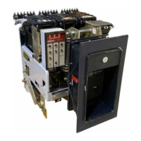
:wt
x,
FINGER-TYPE
PRIMARY
DISCONNECTS
t'
N
r rt{
''f
..PUSH
TO WITHDRAW''
RELEASE
LEVER
\
9
Fig.4
AKR-58-75
manually
operated (substructure
type)
 Loading...