GEI-861518
2. With
the movable inner
housing
of the compartment
in
the
CONNECTED
position,
insert
the racking
handle
(part
no.
673D0500-636-05)
on
the
jackscrew
shaft
located at the
left
side of the
compartment
just
above
the
position
indicator.
3. Rotate
the
handle
counterclockwise
until the
iack-
screw stops
-
the indicator
should read DISC.
4. Remove the racking handle and open the compart-
ment door.
5. Rotate the two
track-lock links and
oull the
rioht
track
to the limit
of
its travel.
6. Using a
lifting device, raise the
breaker
until the
breaker mounting
pins
are approximately one-inch above
the
tracks.
Use care to avoid damage
to the
breaker
wiring.
7. Pull the left track
out
to the limit
of
its travel
and
lower
the
breaker so
its mounting
pins
drop into
the
slots
in the
track.
Remove
the lifting
device.
8.
Push the
breaker
in
against the
track
stops. On electri-
cally operated breakers, be sure to depress
the
spring dis-
charge
lever while
doing so. Rotate
the
two track-lock links to
lock
the breaker
in
place.
Close the compartment door.
9.
Insert the racking handle
on
the
jackscrew
shaft
and
rotate it
clockwise
to move breaker into the compartment.
Breaker is in CONNECTED
position
when
lackscrew
stops.
The indicator
should
read
CONN.
10. Orient the
lackscrew
so
that its
slotted
sleeve
is
free to
move outward, otherwise the
breaker
will remain trip-free.
Breaker Removal
(Code
A)
1
.
Trip the breaker.
Insert
the
racking handle into the
jack-
screw shaft.
2. Rotate the handle counterclockwise untilthe
iackscrew
stops.
Indicator
should read DISC.
3.
Remove the racking handle and
open
the compartment
door.
4. Rotate the two track-lock links and
pull
the breaker out
to the track travel
limit. This is the WITHDRAWN
position.
lf
the breaker
is
electrically operated,
the
breaker-mounted
Spring Discharge lever must be depressed to
permit
with-
drawal.
NOTE: Spring discharge interlocks were
not re-
quired
and are not
present
in existing compart-
ments
originally
furnished for
non-quick-close type
electrically operated AK-751 1
00 breakers.
Regard-
/ess of whether this interlocking hardware is
present
in
a compartment,
ALWAYS verify
that
the
closing spnngs
are
discharged and the breaker is
tripped
OPEN before
removal is
attempted.
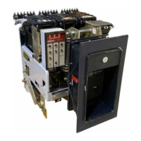
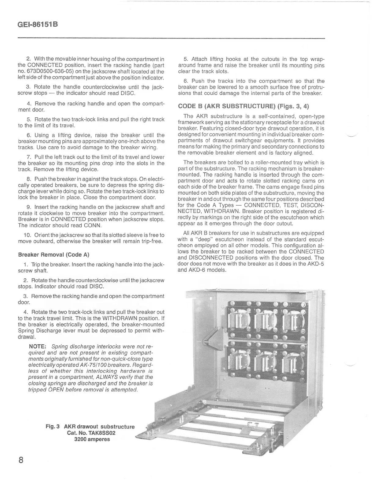
Fig.3
AKR drawout substructure
Cat. No. TAK8SS02
3200
amperes
5. Attach
lifting hooks
at
the
cutouts
in
the top wrap-
around frame
and raise
the breaker
until
its
mounting
pins
clear the track slots.
6.
Push
the
tracks into
the compartment so that
the
breaker
can
be lowered
to a smooth surface
free
of
protru-
sions that
could damage
the internal
parts
of
the breaker.
CODE B
(AKR
SUBSTRUCTURE)
(Figs.3,4)
The AKR
substructure
is
a self-contained,
open-type
framework
serving as the stationary receptacle for
a drawout
breaker. Featuring
closed-door type drawout operation, it is
designed for convenient mounting in individual
breaker com-
partments
of drawout switchgear equipments. lt
provides
means for making the
primary
and secondary connections to
the removable
breaker element and is factory
aligned.
The
breakers are bolted to a roller-mounted
tray which
is
part
of the substructure. The racking
mechanism is breaker-
mounted. The racking handle
is inserted through
the com-
partment
door
and
acts
to
rotate
slotted
racking
cams
on
each
slde of
the
breaker
frame.
The cams engage fixed
pins
mounted
on both side
plates
of the
substructure, moving the
breaker
in
and out through the
same
four
positions
described
for
the Code A Types
-
CONNECTED, TEST,
DISCON-
NECTED, WITHDRAWN. Breaker
position
is registered
di-
rectly
by
markings
on the right side of the
escutcheon which
appear as it
emerges through the door
cutout.
All AKR B
breakers
for
use
in
substructures are equipped
with
a
"deep"
escutcheon instead of the
standard escut-
cheon employed on all oiher models.
This configuration
al-
lows
the
breaker
to be racked
between the CONNECTED
and
DISCONNECTED
oositions
with the
door closed. The
door does not move with the
breaker as
it
does
in
the AKD-S
and AKD-6 models.
$
'$
]$
$.
'e
i:
$
*
8
 Loading...