Installation instructions.
22
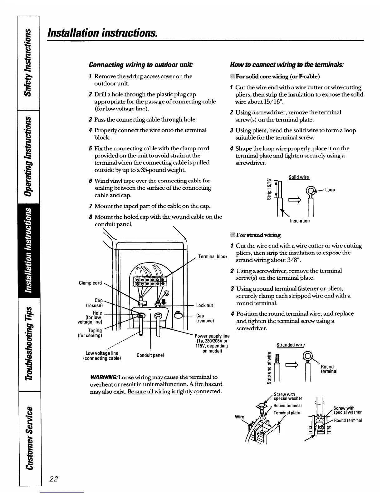
Connecting wiring to outdoor unit:
1
2
3
4
5
6
7
8
Remove the wiring access cover on the
outdoor unit.
Drill a hole through the plastic plug cap
appropriate for the passage of connecting cable
(for low voltage line).
Pass the connecting cable through hole.
Properly connect the wire onto the terminal
block.
Fix the connecting cable with the clamp cord
provided on the unit to avoid strain at the
terminal when the connecting cable is pulled
outside by up to a 35-pound weight.
Wmd vinyl tape over the connecting cable for
sealing between the surface of the connecting
cable and cap.
Mount the taped part of the cable on the cap.
Mount the holed cap with the wound cable on the
conduit panel. -
\
\
Clamp cord
!
Cap
(resuse)
4
Hole
(for low
voltage line)
Taping
J
(for sealing)
11
\
1
, Terminal block
/1
Low voltage line
(connecting cable)
Conduit panel
How to connect wiring to the terminals:
~~’~
For solidcorewiring (orFable)
1
2
3
4
Cut the wire end with a wire cutter or wirtiutting
pliers, then strip the insulation to expose the solid
wire about 15/16”.
Using a screwdriver, remove the terminal
screw(s) on the terminal plate.
Using pliers, bend the solid wire to form a loop
suitable for the terminal screw.
Shape the loop wire properly, place it on the
terminal plate and tighten securely using a
screwdriver.
Solid wire
‘m
~
n
‘! r
Loop
.—
~
w
Q
Insulation
;
Forstrandwiring
2
3
Lock nut
- Cap
4
(remove)
Power supply line
(10, 230/208V or
115V, depending
on model)
W!AR/U/NG:Loose
wiringmay cause the terminal to
overheat or result in unit malfimction. A fwe hazard
may also exist. Be sure all wiring is ti~htlv connected.
Cut the wire end with a wire cutter or wire cutting
pliers, then strip the insulation to expose the
strand wiring about 3/8”.
Using a screwdriver, remove the terminal
screw(s) on the terminal plate.
Using around terminal fmtener or pliers,
securely clamp each stripped wire end with a
round terminal.
Position the round terminal wire, and replace
and tighten the terminal screw using a
screwdriver.
Stranded wire
, Screw with
/ sDecial washer
I I
terminal
Screw with
Wi
al plate
special washer
Round terminal