Installation instructions.
El
Form thepipingsbywrappingtheconnecting
portion of theindoor unitwithinsulation
matexial and secure
itwithtwoplasticbands
(for therightpipings).
If you want to connect an additional drain
hose, the end of the drain outlet should be
routed above the ground. Secure the drain line
appropriately.
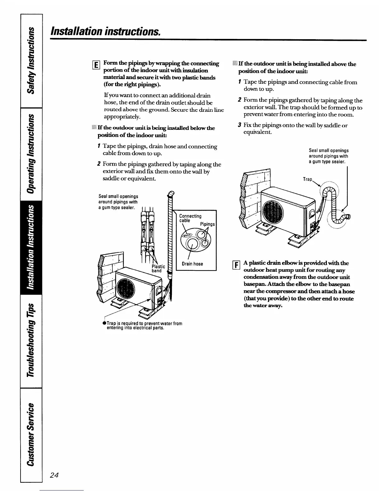
;: If the outdoor unit is being installed below the
positionof theindoor unk
1
2
Tape the pipings, drain hose and connecting
cable fi-om down to up.
Form the pipings gathered by taping along the
exterior wall and fix them onto the wall by
saddle or equivalent.
around pipings with
a gum type sealer.
Drain hose
●Trap is required to prevent water from
entering into electrical parts.
24
!’: H
the outdoor unitisbeing installedabove the
positionof theindoor uniti
1 Tape the pipings and connecting cable horn
down to Up.
2 Form the pipings gathered by taping along the
exterior wall. The trap should be formed up to
prevent water from entering into the room.
3 Fix the pipings onto the wall by saddle or
equivalent.
Seal small openings
around pipings with
a gum type sealer.
❑
A plasticdrainelbow is provided withthe
outdoor heat pump unitfor routingany
condensationawayfi-omtheoutdoor unit
basepan.Attach the elbow to thebasepan
nearthecompressor and thenattachahose
(thatyou provide) to the other end to route
thewateraway.