– 37 –
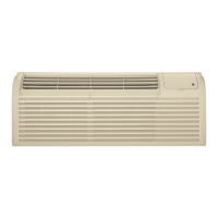
5. Remove the 11 Phillips-head screws and the
divider assembly from the left and right side of
the unit.
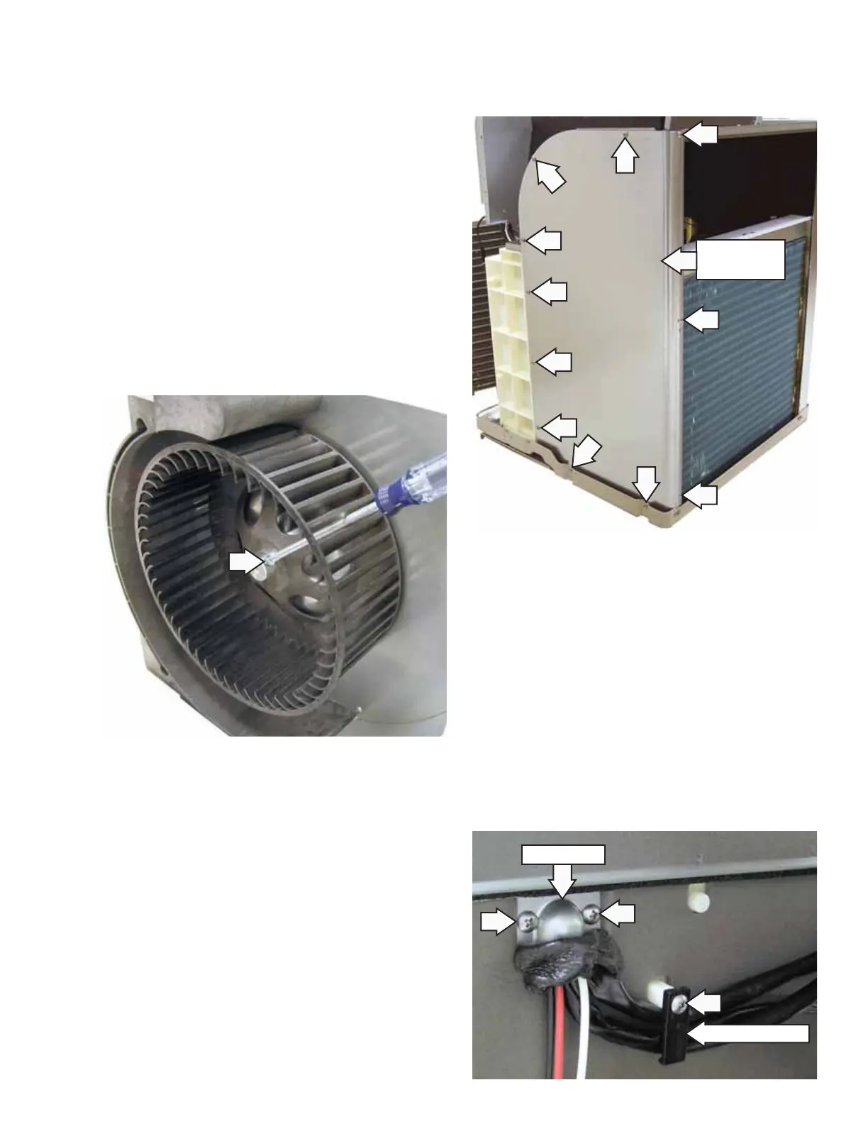
Note: Position blower wheel setscrew on the fl at
side of the motor shaft when assembling.
6. Disconnect the indoor fan wire connector
(CN103) from the drive board. (See
Circuit Boards
Locator Views.)
7. Cut off plastic wire ties that retain indoor fan
motor wiring.
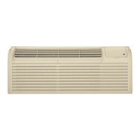
8. Remove the Phillips-head screw that attaches
each of the 2 wire retainers to the back of the
indoor fan housing.
9. Remove the seal, 2 Phillips-head screws, and the
wire cover.
10. Pull the fan motor wires through the opening.
To remove the indoor fan motor:
1. Remove the unit from the cabinet. (See
Slide-Out
Chassis.)
2. Remove the electronics cover. (See Main Board.)
Note: It may be helpful to observe the appearance
of the bundled wiring behind the electronics
cover. (See Drive Board.) In the following steps, it
will become necessary to cut off plastic wire ties
that fasten wiring together. Bundle wiring before
installing the electronics cover.
3. Remove the resistance heaters. (See Main Board.)
4. Loosen the Phillips-head setscrew securing
the blower wheel. Pull the blower wheel off the
motor shaft.
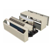
Retainer (1 of 2)
Wire Cover
Right Divider
Assembly
(Continued next page)