EasyManua.ls Logo

GE AZ45E07DA Series - User Manual

GE AZ45E07DA Series
64 pages
Print Icon
To Next Page IconTo Next Page
Loading...
2016 Zoneline Air Conditioner
GE Appliances
Louisville, Kentucky 40225
31-9252
Technical Service Guide
April 2016
GE Appliances
230/208 VOLT MODELS
AZ45E07DA_ _1
AZ65H07DA_ _1
AZ45E09DA_ _1
AZ65H09DA_ _1
AZ45E12DA_ _1
AZ65H12DA_ _1
AZ45E15DA_ _1
AZ65H15DA_ _1

Table of Contents

Question and Answer IconNeed help?

Do you have a question about the GE AZ45E07DA Series and is the answer not in the manual?

GE AZ45E07DA Series Specifications

General IconGeneral
BrandGE
ModelAZ45E07DA Series
CategoryAir Conditioner
LanguageEnglish

Summary

Safety Requirements and Procedures

Safety Equipment and LOTO

Required personal protective equipment for repairs and the Lockout/Tagout (LOTO) procedure.

System Pressures and Tools

System Pressures

Operating pressures for R-22 and R-410A systems relevant to Zoneline units.

Tools Required

List of tools necessary for servicing Zoneline units.

Introduction to Zoneline

Nomenclature Breakdown

Zoneline Operation Modes

Cooling and Heating Modes

How Zoneline units function in cooling and heating, including AZ6500 stages.

Special Heating Modes

Heat Pump Lockout and Boost Heat

Modes to disable heat pump or provide supplementary heat.

Fan Cycle Operation

Fan Cycle Modes

Fan cycling behavior in Cooling, Resistance Heating, and Heat Pump modes.

Constant Fan Mode

Random Restart Function

Restart Logic

Unit restart behavior after power outages, including AZ6500 specifics.

Freeze Prevention for Indoor Coil

Indoor Coil Overheat Protection

Reverse Cycle Defrost

ICR System

Auxiliary Controls

Configuration Options

Accessing and configuring modes via AUX SET, including specific settings.

External Connections

CDC and Remote Thermostat

Connecting Central Desk Control and remote thermostats for expanded functionality.

Main Board

Component Identification

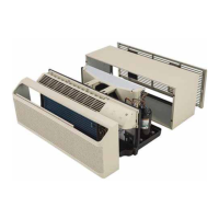
Overview, front cover components, and detailed connector labels on the main board.

Component Checks

Service Main Board Configuration

DIP Switch Settings

How to configure the service board using DIP switches for model and BTU settings.

User Interface

Louvers Adjustment

Thermistors

Indoor & Outdoor Details

Function, location, and resistance values for indoor and outdoor thermistors.

Sealed System Components

Indoor Fan Motor

Outdoor Fan Motor

Heater Assembly

ICR System Operation

Make-Up Air Module (MUAM)

Operation & Controls

Module function, mounting, switches, and operational conditions.

Sealed System Heat Pump

Compressor Wiring Check

Instructions for checking compressor windings and wiring safety.

Sealed System Service

High Pressure Switch & Drier

Function and replacement procedures for high pressure switch and drier.

Electrical Components

Capacitor Safety

Safety precautions for discharging the capacitor before service.

Low Voltage Transformer Details

Condensate Removal

Fault Codes

Troubleshooting Guide

Comprehensive list of fault codes, their meanings, effects, and reset conditions.

Service Mode

Refrigerant Flow

Cooling Mode

Diagram illustrating refrigerant flow during cooling mode.

Heating Mode

Diagram illustrating refrigerant flow during heat pump mode.

Recovery Process

Charging Summary

Wiring Diagrams

Early & Latest Models

Wiring diagrams for early and latest production Zoneline models.
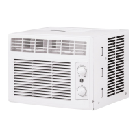
MUAM Wiring Diagram

New Accessories

Warranty Information

Related product manuals