– 40 –
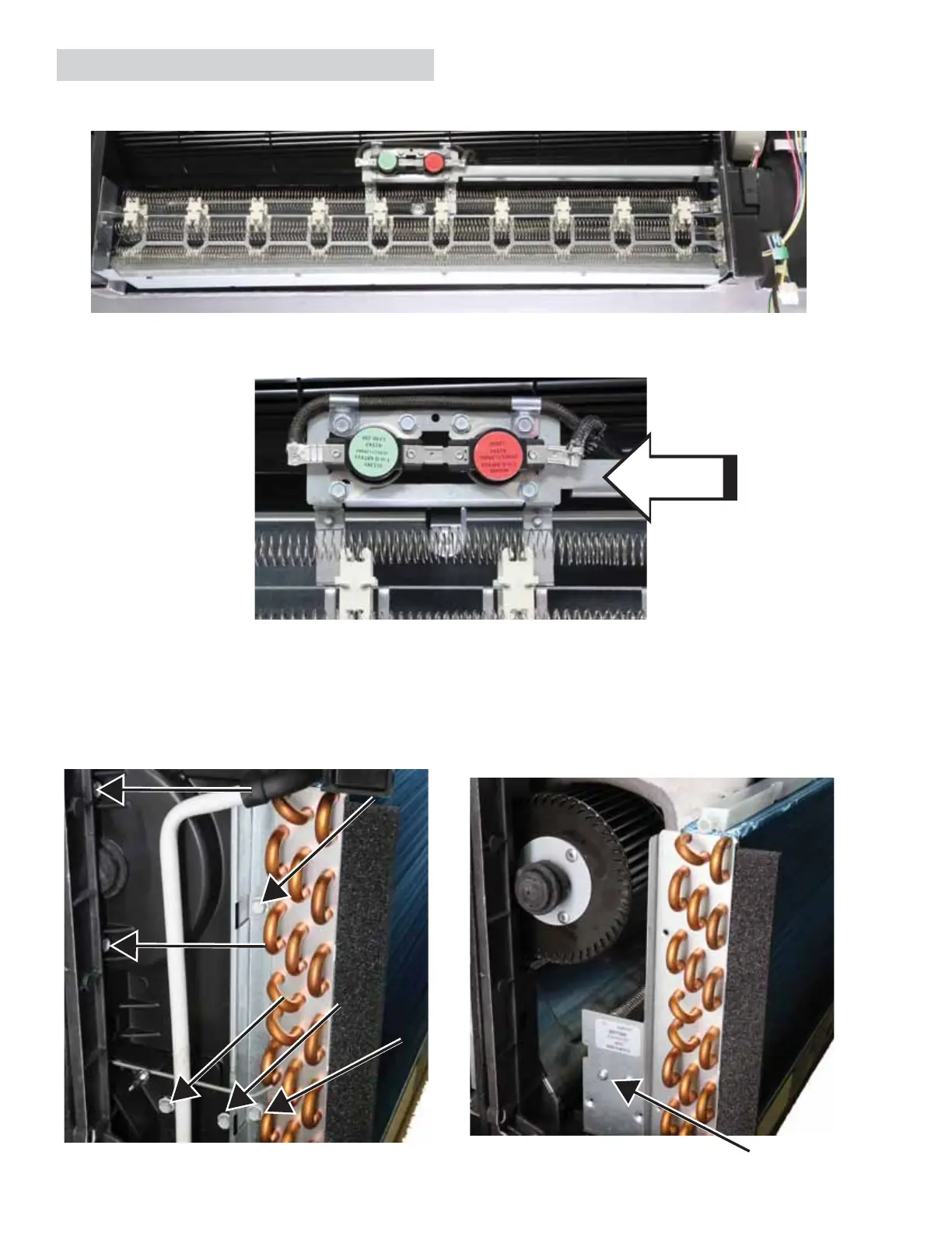
The heater assembly sets on the base pan and is secured by two screws on the left end cap.
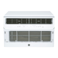
The thermal cut-outs are part of the heater assembly. They can be replaced separately if needed.
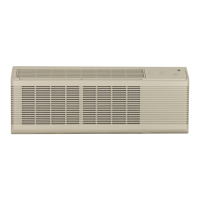
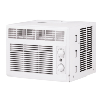
Heater Assembly
Remove six screws to remove the end cap to access the heater assembly. Two screws are used to secure
the bracket attached to the indoor coil and end cap. After disconnecting the wire harness from the board
and removing one ground screw, the heater assembly will slide out the left side of the Zoneline.
Heater
Heater Assembly
NOTE: Some
models have an
additional inline
fuse to the heater
assembly. If this
fuse opens, replace
the complete heater
assembly, as the
fuse is not available
separately.
Fuse
located in
wire cover
 Loading...