– 43 –
Thermistors
The main board uses input from 3 thermistors.
These thermistors are located on the indoor
coil, outdoor coil, and outdoor fan shroud. (See
Component Locator Views.) The main board monitors
the thermistors to determine the temperature in
these areas and uses this information to make
operating decisions.
For information regarding the optional room air
sensor (kit), refer to the Room Air Sensor section.
(See
Features and Operation.)
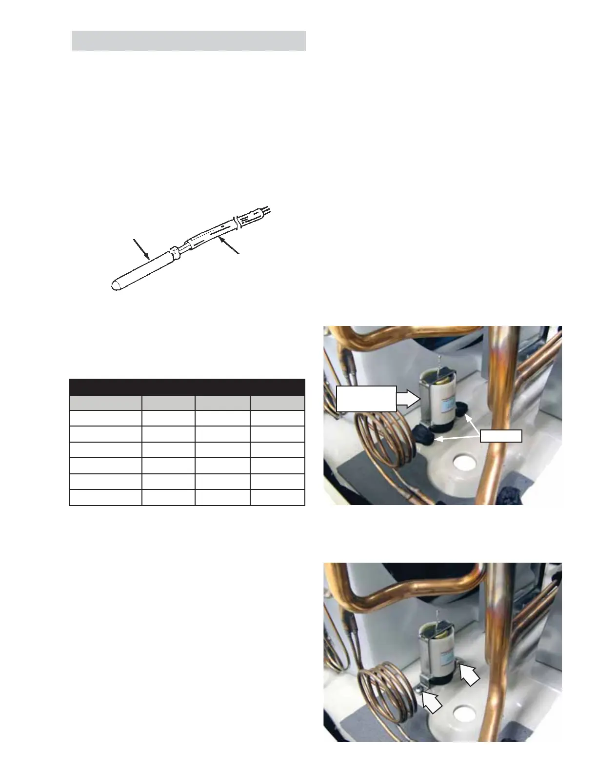
THERMISTOR
LEADS
The thermistors can be checked to determine if
they are good. Below is a chart showing thermistor
resistance values at various temperatures.
Thermistor Chart
Thermistor Resistance (Ohms)
Temperature I.D. COIL O.D. Coil Outdoor
10°F 94900 27930 27930
30°F 51940 15420 15420
32°F 49330 14580 14580
50°F 29960 8860 8860
70°F 17930 5280 5280
90°F 10970 3320 3320
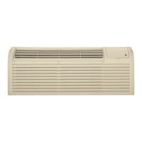
Thermostatic Drain Valve
During the cooling season, the thermostatic drain
valve remains closed to allow water to accumulate
in the base pan. The water is then picked up by the
outdoor fan blade and blown into the condenser,
providing more effi cient cooling. During heat pump
season the thermostatic drain opens to allow water
to drain from the base pan prior to freezing. This pre-
vents the outdoor fan blade from scraping against
ice that could freeze in the bottom of the base pan.
The thermostatic drain valve is operated by a self-
contained thermostat. The thermostat begins to
open the drain valve at approximately 58°F and will
be fully open at approximately 45°F.
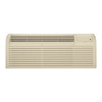
To remove the thermostatic drain valve:
1. Remove the unit from the cabinet. (See
Slide-Out
Chassis.)
2. Remove the left divider assembly.
3. Remove the sealant covering the screws.
4. Remove the 2 Phillips-head screws that attach
the thermostatic drain valve to the base pan.
Thermostatic
Drain Valve
Sealant