– 48 –
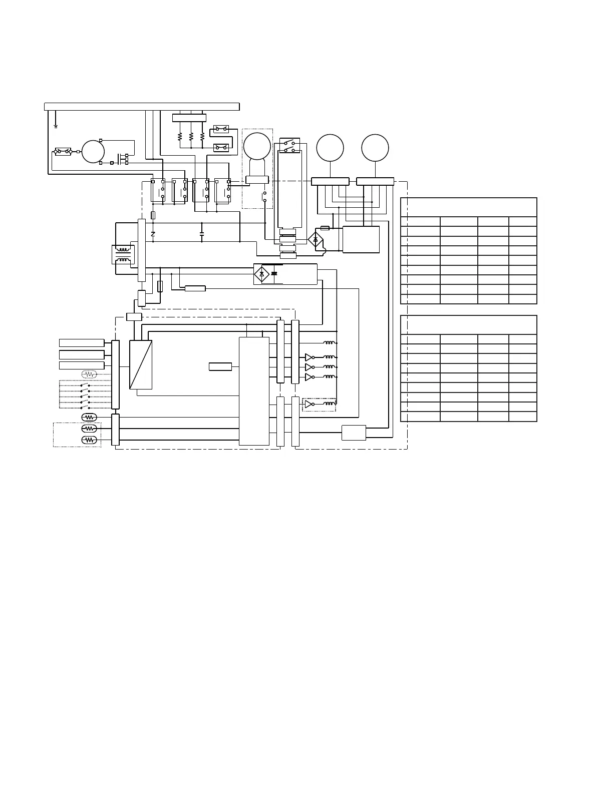
8500 Series Typical Schematic
Refer to the mini-manual attached to the unit.
Note: Refer to Yellow Universal Connector
Temperature limiting during HEAT mode
(all temperatures shown in °F)
UP Down Min. Max.
NONE 4,5,6 60° 85°
4 5,6 60° 80°
4,5 6 60° 78°
5 4,6 60° 76°
5,6 4 60° 74°
4,5,6 NONE 60° 72°
4,6 5 60° 70°
6 4,5 60° 65°
*1
CN109
CN107
CN108
Reverse
Valve
Sol.
SW201
RY104
RY102
HEATER
HEATER
HEATER
PROTECTOR
FUSE
RY103
RY101
FU101
(NR101)
Varistor
(C101, C101A,C102)
Capacitor
TRANSFORMER
CN101
Motor
Comp.
C
R
S
Running
Capacitor
O.L.P.
UNIVERSAL CONNECTOR
*2
DRIVE BOARD UNIT
RY105
*3
FU102
CN102
Outdoor
Fan
Motor
CN103
Indoor
Fan
Motor
FU103
BCN106
AC CLOCK
BCN105
SWITCHING
POWER SUPPLY
15V
SWITCHING
POWER SUPPLY
12V
CN6
RY104
RY103
RY102
RY101
CIRCUIT
CONTROL
MAIN BOARD UNIT
DIP SW
(for setting)
CN5
CN4
RY105
BCN104
ISOLATER
CN3
Room Air Sensor Kit
IR Motion Sensor
OUTDOOR
CDC Switch
CN1
ID.COIL
OD.COIL
Door Switch
R
GL
GH
B
Y
W
*2: Only C101 is used for 208/ 230V models and both
C101A and C102 are used for 265V models
*1: Only included in 85H models
*3:There is internal O.L.P in AZ85H18DAC/AZ85E18DAC
*1
*1
Temperature limiting during COOL mode
(all temperatures shown in °F)
UP Down Min. Max.
NONE 1,2,3 60° 85°
1 2,3 64° 85°
1,2 3 66° 85°
2 1,3 68° 85°
2,3 1 70° 85°
1,2,3 NONE 72° 85°
1,3 2 74° 85°
3 1,2 76° 85°