– 8 –
Technical Data
DISCONNECT POWER BEFORE SERVICING
IMPORTANT - RECONNECT ALL GROUNDING DEVICES
All parts of this appliance capable of conducting electrical current are
grounded. If grounding wires, screws, straps, clips, nuts or washers used to
complete a path to ground are removed for service, they must be returned
to their original position and properly fastened.
WARNING DISCONNECT UNIT FROM ELECTRICAL POWER SUPPLY
BEFORE MAKING ANY ELECTRICAL CHECKS.
MAXIMUM CURRENT LEAKAGE: 0.75 MILLIAMP
MAXIMUM GROUND PATH RESISTANCE: 0.1 OHM
IMPORTANT SAFETY NOTICE
This information is intended for use by individuals possessing adequate backgrounds
of electrical, electronic and mechanical experience. Any attempt to repair a major
appliance may result in personal injury and property damage. The manufacturer
or seller cannot be responsible for the interpretation of this information, nor can it
assume any liability in connection with its use.
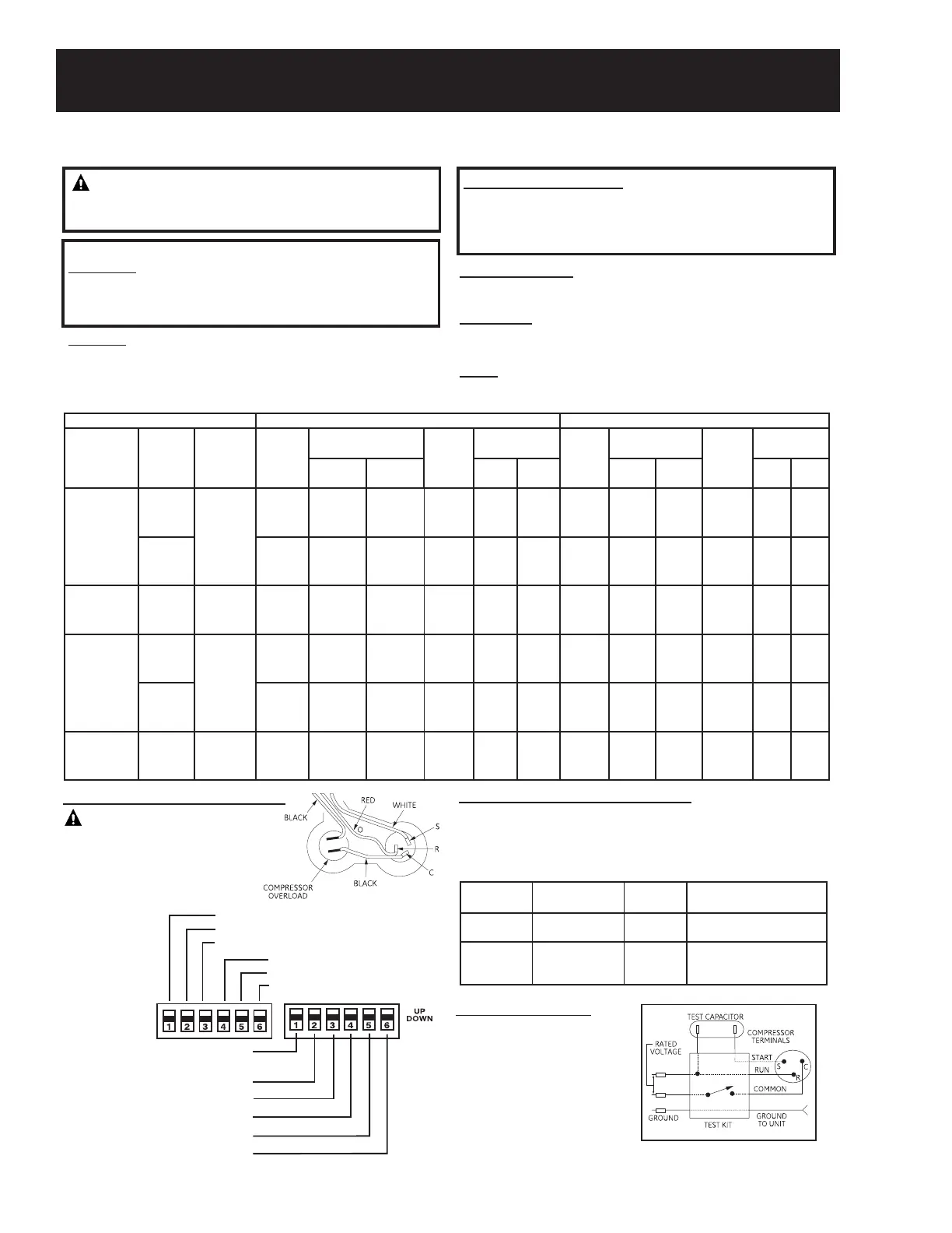
COOLING R/C HEATING
MODEL
RATED
VOLTAGE
VOLTAGE
LIMITS
EVAP
AIR
TEMP
IN °F
EVAP AIR OUT °F
AIR
TEMP
COND.
IN °F
COOLING
CURRENT
EVAP
AIR
TEMP
IN °F
EVAP AIR OUT °F
AIR
TEMP
COND.
IN °F
CURRENT
MIN. MAX. MIN. MAX. MIN. MAX. MIN. MAX.
AZ85H09D
208V
187-253
70
80
90
74
83
90
82
89
98
80
95
110
3.5
3.9
3.9
3.9
4.4
4.6
70
75
80
112
117
121
121
126
131
47
60
75
3.3
3.4
3.4
3.9
4.0
4.1
230V
70
80
90
74
83
90
82
89
98
80
95
110
3.2
3.6
3.6
3.6
4.1
4.2
70
75
80
112
117
121
121
126
131
47
60
75
3.1
3.1
3.2
3.6
3.7
3.8
AZ85H09E 265 238-292
70
80
90
74
83
90
82
89
98
80
95
110
2.8
3.1
3.1
3.1
3.5
3.7
70
75
80
112
117
121
121
126
131
47
60
75
2.7
2.7
2.7
3.1
3.2
3.3
AZ85H12D
208V
187-253
70
80
90
74
82
89
82
90
96
80
95
110
4.4
4.8
5.4
5.1
5.7
6.5
70
75
80
117
120
125
126
131
136
47
60
75
4.1
4.3
4.5
4.8
5.1
5.4
230V
70
80
90
74
82
89
82
90
96
80
95
110
4.1
4.4
5.0
4.7
5.3
6.0
70
75
80
117
120
125
126
131
136
47
60
75
3.8
3.9
4.2
4.5
4.7
5.0
AZ85H12E
265 187-
253
238-292
70
80
90
74
82
89
82
90
96
80
95
110
3.5
3.9
4.3
4.1
4.6
5.2
70
75
80
117
120
125
126
131
136
47
60
75
3.3
3.4
3.6
3.9
4.1
4.3
POWER SUPPLY AND TEMPERATURE CHECK
RUNNING CURRENT
With unit in case, operate for ten minutes on Hi-Cool. See Power Supply
and Temperature Check table for normal limits.
CONDENSER
1. Check for blockage with dirt, or other material.
2. Check for corrosion.
FILTER
Check for cleanliness.
TEMPERATURE DIFFERENTIAL - COOLING
Unit must operate for one hour with thermostat at coldestsetting
prior to measuring air temperatures. See Power Supply and
Temperature Check table for normal limits.
SEALED SYSTEM
MODEL COMPRESSOR
REFRIG.
R410A
CAPILLARY
OD x ID x LENGHT (PC)
AZ85H09D
AZ85H09E
Rechi 34 oz.
.106" x .055" x 15.75" (3)
.106" x .055" x 31.50" (1)
AZ85H12D
AZ85H12E
Rechi 39 oz.
.106" x .055" x 15.75" (4)
.106" x .059" x 9.84"(1)
.106" x .059" x 25.59" (1)
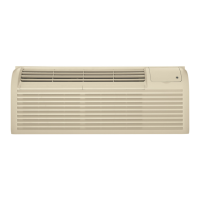
RUN CAPACITOR CHECK
1. Replace unit run capacitor with
a known good test capacitor
which may be 10 MFD higher
than speci¿ed and attempt to
start compressor.
2. If compressor starts, install a
new run capacitor which has
a rating speci¿ed for the unit.
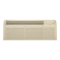
TL1 (C) (Temp. Limit 1 - Cool)
TL2 (C) (Temp. Limit 2 - Cool)
TL3 (C) (Temp. Limit 3 - Cool)
TL1 (H) (Temp. Limit 1 - Heat)
TL2 (H) (Temp. Limit 2 - Heat)
TL3 (H) (Temp. Limit 3 - Heat)
ALL I'R (All Electric Heat
(Heat-pump models only)
FREEZ S (Freeze Sentinel)
CONST FAN (Constant ON Fan)
OCCUPIED (Occupancy Sensor)
DUCT (Blower Fan)
No Function
(Reserved for future use)
WARNING: Risk of electric shock. Can cause injury
or death: Read all instructions and safety information
before servicing this product.
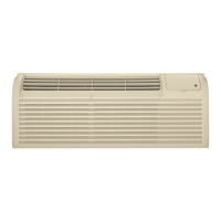
WIRING - COMPRESSOR DIRECT CHECK
CAUTION: Risk of injury. Keep
head clear of terminal area when
cover is removed.
Check windings ¿rst. If open or
grounded, DO NOT apply power to
compressor terminals.
Heat Pump Model AZ85H12DACW1
(Continued next page)