210572107 Rev. C 1-08
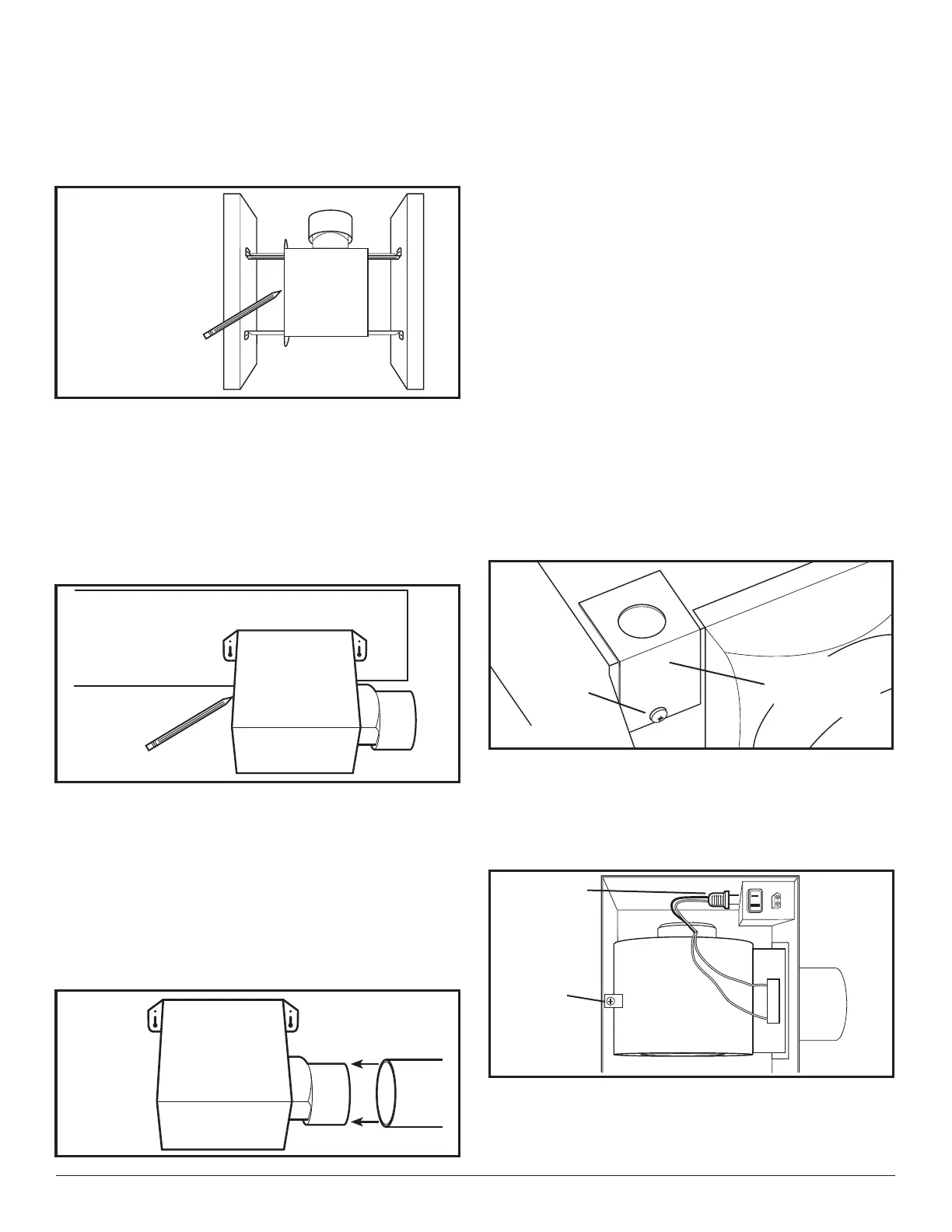
opening, being careful not to cut or damage any
electrical or other hidden utilities. Install the rails on
the housing and position the housing in the previously
cut hole so that it is flush with the finished ceiling.
Secure the ends of the rails to the joists with nails
or screws (not provided) (Figure 1).
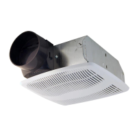
1b. Mounting Tab Installation: Position housing against
the joist and trace an outline of the housing onto the
ceiling material (Figure 4). Set housing aside and cut
opening, being careful not to cut or damage any
electrical or other hidden utilities. Place housing next
to the joist and insure that it is flush with the finished
ceiling. Secure with four nails or screws (not provided)
to ensure proper installation (Figure 2).
SECTION 4
Ducting
CAUTION: ALL DUCTING MUST COMPLY WITH
LOCAL AND NATIONAL BUILDING CODES.
1. Connect the ducting to the fan’s duct collar (Figure
5). Secure in place using tape or screw clamp. Always
duct the fan to the outside through a wall or roof cap.
NOTE: If damper detaches from unit, reattach by
snapping the collar back onto the unit. It is designed to
only fit one way.
SECTION 5
Wiring
CAUTION: MAKE SURE POWER IS SWITCHED OFF
AT SERVICE PANEL BEFORE STARTING INSTALLATION.
CAUTION: ALL ELECTRICAL CONNECTIONS MUST
BE MADE IN ACCORDANCE WITH LOCAL CODES,
ORDINANCES, OR NATIONAL ELECTRICAL CODE. IF YOU
ARE UNFAMILIAR WITH METHODS OF INSTALLING
ELECTRICAL WIRING, SECURE THE SERVICES OF A
QUALIFIED ELECTRICIAN.
NOTE: This unit includes a side access panel for wiring
that does not require the removal of the fan’s blower
assembly. If you choose to wire the unit from the inside,
you will need to remove the blower assembly and internal
wiring compartment. Both methods are equally effective.
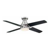
1a. External Wire Compartment: Remove the wire
compartment cover screw and place cover in a
secure place (Figure 6).
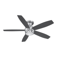
1b. Internal Wire Compartment: Remove the screw holding
the blower assembly in place. Lift up on the assembly
and tilt it at a 45° angle to remove from the housing
(Figure 7). Remove the wire compartment cover screw
and place the cover in a secure place (Figure 8).
3 of 8
Figure 3
Figure 4
Figure 5
Figure 6
Screw
Wire
Compartment
Cover
Figure 7
Plug
Screw
www.geelectrical.com