2-4 Issue 01, 04/05 CL 5
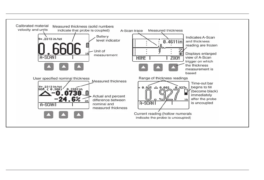
Interpreting Display Screens
Understanding the Keypad, Menu System, and Displays
FIGURE 2-2MEASUREMENT DISPLAY MODE The displays appearance varies based on installed instrument
options as well as instrument display settings. NORMAL view mode is available in all instruments regardless of the
installed options. Additional measurement view modes are available when the A-Scan or Data Recorder options are
installed. Depending on the view selected, the display may contain the current thickness value, a live A-Scan,
minimum thickness value, maximum thickness value, and differential value in the unit of measurement or as a
percentage when compared to a nominal value.
2-4 Issue 01, 04/05 CL 5
Interpreting Display Screens
Understanding the Keypad, Menu System, and Displays
FIGURE 2-2MEASUREMENT DISPLAY MODE The displays appearance varies based on installed instrument
options as well as instrument display settings. NORMAL view mode is available in all instruments regardless of the
installed options. Additional measurement view modes are available when the A-Scan or Data Recorder options are
installed. Depending on the view selected, the display may contain the current thickness value, a live A-Scan,
minimum thickness value, maximum thickness value, and differential value in the unit of measurement or as a
percentage when compared to a nominal value.