Do you have a question about the GE CR307-CR308 Series and is the answer not in the manual?
Features a strongbox coil design for durability.
Adjustable trip current ±10% without changing heaters.
Indicates when the overload relay has tripped.
Features straight through wiring for ease of installation.
Terminals accommodate up to #4 wire for flexible connections.
Starter can be disassembled for inspection in seconds.
Prevents opening enclosure door when handle is in OFF position.
Remove all packing materials before connecting the starter.
Clean magnet mating surfaces of dust or foreign matter.
Select heaters according to the accompanying heater table.
Operate magnet and arm to ensure free movement.
Mount the starter on a sturdy vertical support.
Reset overload relay manually by depressing the reset arm.
Ensure motor branch circuit protection per National Electrical Code.
Always remove power from the device before removing the coil.
Press against coil and pull up coil retainers to release.
Remove magnet assembly, coil, and movable arm.
Remove spring clip and armature from movable arm.
Remove the coil from the magnet assembly.
Replace the coil following the reverse procedure.
Inspect and replace movable contacts quickly without tools.
Ensure dependable service with basic preventive maintenance tasks.
Check for welded relay contacts using an audible click or continuity test.
Do not file contacts; replace when silver tip is nearly gone.
Adjust ultimate tripping current ±10% using the adjustment dial.
This document describes the GEH-4776 Installation Instructions for NEMA Size 2 300/400-Line Combination Magnetic Starters, covering CR307-CR308, CR310-CR311, CR387, CR390, CR407-CR408, CR410-CR415, CR487, CR490, CR492, and CR494 Series.
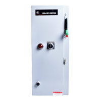
The ABB 300-Line full voltage magnetic combination starter integrates a magnetic contactor, a three-leg block overload relay, and a manually operated circuit breaker or disconnect switch. The disconnect switch, which can be either fusible or non-fusible, provides a manual means of disconnecting the motor from the line. Both the circuit breaker and fusible disconnect switch offer motor branch short-circuit protection. The overload relay provides crucial motor protection against both running and stalled motor overload conditions.
| Brand | GE |
|---|---|
| Model | CR307-CR308 Series |
| Category | Controller |
| Language | English |