GE MEDICAL SYSTEMS CT PROSPEED SERIES INSTALLATION
2124011
3-5
REV 15
3–1–1 Setting Coupling Terminal for Input Voltage (continued)
8. Set the voltage in the Power Distribution Unit (PDU) as follows:
a. Check the supplied voltage at Power Distribution Box.
Eight (8) levels of input RATING voltage (480, 460, 440, 415, 400, 380, 208, 200V) can be handled.
NOTICE
Input Voltage 208 V or 200 V can not be used for systems having a 350 mA/120 kV output.
NOTICE
For the System installed in the U.S.A., only 480V can be used as a PDU input voltage.
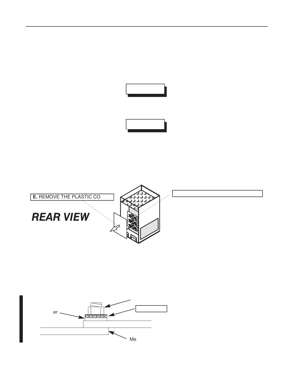
b. Remove the plastic cover from the transformer coupling plate ; See Illustration 3–2 (E).
c. Set
the PDU input RA
TING voltage according to the appropriate setting shown in Illustration 3–3
Illustra
-
tion 3–10.
The voltage is set by metal tap plates on the transformer coupling plate. See Illustration 3–2 (F).
F
.
TRANSFORMER COUPLING PLATE
E.
REMOVE THE PLASTIC COVER
POWER DISTRIBUTION UNIT REAR VIEW
ILLUSTRA
TION 3–2
Note
All connection types are delta. Therefore, there is no N(neutral) pin.
Nut
Star Washer
Plain Washer
Metal Tap Plate
Notice!:
The star washer MUST be
installed between nut and plain
washer to prevent loosening.
If the nut is loosened, a large
contact resistance might cause
the attaching parts to burn out.
 Loading...


