GE MEDICAL SYSTEMS CT PROSPEED SERIES INSTALLATION
2124011
3-4
REV 15
3–1–1 Setting Coupling Terminal for Input Voltage (continued)
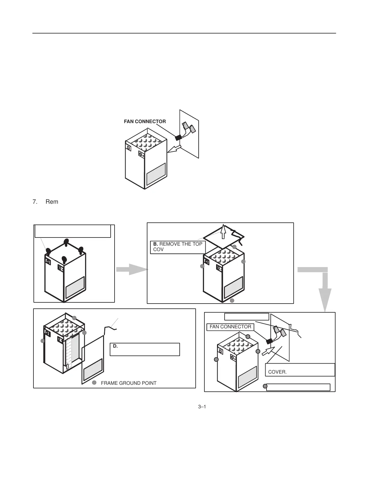
6. Remove the rear cover, after removing the fan connector (brown connector) and the ground cable.
See Illustration 3–1 (C).
a. Verify
that the rear cover is installed in step, and that the fans’ connector is properly
connected before applying
power to PDU.
FAN
CONNECT
OR
7. Remove the right side cover, after removing the fan connector (brown connector) and the ground cable.
See Illustration 3–1 (D).
A.
REMOVE FOUR(4) HOIST
RINGS.
GROUND CABLE
: FRAME GROUND POINT
C. REMOVE THE REAR
COVER.
F
AN CONNECT
OR
B. REMOVE THE TOP
COVER.
: FRAME GROUND POINT
GROUND CABLE
: FRAME GROUND POINT
D.
REMOVE THE RIGHT
SIDE COVER.
POWER DISTRIBUTION UNIT FRONT VIEW
ILLUSTRA
TION 3–1
 Loading...


