GE MEDICAL SYSTEMS CT PROSPEED SERIES INSTALLATION
2124011
3-3
REV 15
3–1 POWER DISTRIBUTION UNIT (PDU)
Note
This section applies to PDUs whose model number is 2121798.
3–1–1 Setting Coupling Terminal for Input Voltage
Install the PDU (Illustration 3–1 X Illustration 3–10) as follows:
1. Move the PDU to its installation position.
2. Verify that there is enough clearance around the PDU for service access.
3. Turn
the four adjustment legs located by the
front and rear casters so that they contact the floor (so that the PDU
does not slide).
4. Remove four(4) hoist rings from the PDU ; See Illustration 3–1 (A).
Note
Do not discard away these four(4) hoist rings.
5. Remove the top cover after removing the ground cable.
See Illustration 3–1 (B).
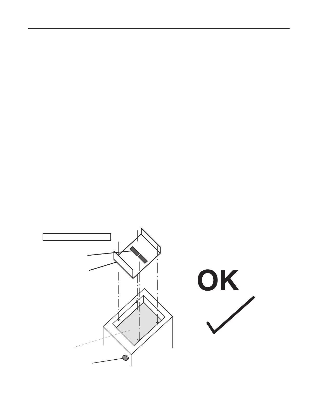
Verify that a protection cover (transparent, plastic) is installed over the circuit board (PANEL COMMON PDU
BOARD).
a. Verify that the WARNING label of the cover is face up so that the air flow from the fans is not obstructed.
CORRECT ATTACHMENT
EMERGENCY STOP SW
DC SUPPLY BOARD
PLASTIC COVER
W
ARNING LABEL
 Loading...


