GE MEDICAL SYSTEMS CT PROSPEED SERIES INSTALLATION
2124011
3-36
REV 15
3–7–2 OC Modification (continued)
4. Power cable Connection in OC
a. Four
power cables are provided, one Black long cable, one Black short cable, one White long cable and one
White short cable.
b. Connect the four power cables as shown in Illustration 3–26.
5. Signal Cable connection
a. Connect the OC internal cables by referring to Illustration 3–24. (There are 12 cables.)
b. Unscrew the DC III rear cover’s 4 screws and remove the rear cover.
c. Connect
the signal cable (for DC III control) and
the video signal cable to the DC III. See Illustration 3–26 and
3–27.
The video signal cable goes to the Video Amp of the DC III.
The signal cable for DC III control goes to CN2 of DCCM2 ASSY of the DC III.
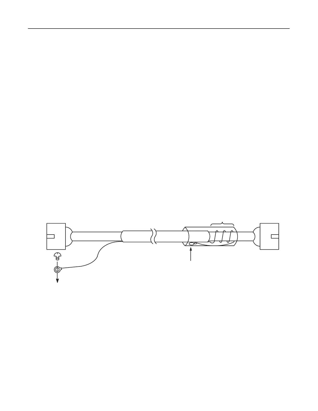
This
signal cable has a ground line. Connect this ground line to the screw which is fixed to the OC nest. T
wist
the
ground line for the DC III side around the signal cable, then cover it with vinyl tape for isolation. See Illus
-
tration 3–25.
FIX THE GROUND TERMINAL WITH SCREW
FROM THE MAIN NEST OF THE OC.
TO
OCCM4
CN5
TO
DCCM2
CN2
TWISTED
FIX THE GROUND TERMINAL
WITH VINYL TAPE FOR ISOLATION.
DC
III
SIGNAL
CABLE FOR DC III
ILLUSTRA
TION 3–25
 Loading...


