D20 ME
Quick Start Guide
GE Power Systems
D20 ME Jumper Options, Continued
Table: VME
Jumper
Options
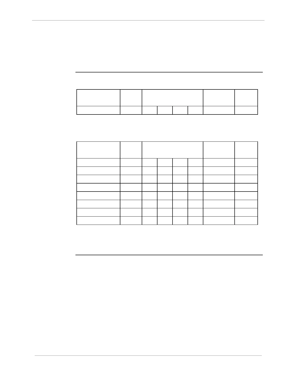
The following tables summarize the jumper settings for each board function
and position that is installed in a CCU for D20 or D200:
Single Node
For D20 or D200:
Board Function JP1
Master /
Slave
JP2
VME Address Bits
4 3 2 1
JP3-1
RTC -
SERCLOCK
JP3-2
RTC -
BRTC
Single Node OUT IN IN IN IN OUT IN
Multi-Node
For D20 or D200:
Board Function JP1
Master /
Slave
JP2
VME Address Bits
4 3 2 1
JP3-1
RTC -
SERCLOCK
JP3-2
RTC -
BRTC
Node #1 OUT IN IN IN OUT IN IN
Node #2 IN IN IN OUT IN IN OUT
Node #3 IN IN IN OUT OUT IN OUT
Node #4 IN IN OUT IN IN IN OUT
Node #5 IN IN OUT IN OUT IN OUT
Node #6 IN IN OUT OUT IN IN OUT
Node #7 IN IN OUT OUT OUT IN OUT
Node #8 IN OUT IN IN IN IN OUT
Notes:
• Single Node is the factory default configuration
• If you have a single-node implementation with Ethernet or Memory expansion or
both, configure jumpers as Single Node
994-0025-1.00-8 General
5
Full Release