GE Power Systems
D20 ME
Quick Start Guide
D20 ME Jumper Options, Continued
JP1 -
VME Control
This jumper sets the Master or Slave function of the board on the VME bus.
Note: Single-node D20 systems are always set to Master.
JP2 -
VME Address
JP2 is a group of four jumpers that set the VME bus address of the board. The
address should reflect the board location in a D200 CCU chassis.
Example: The board with address 1 will be the lead node, with nodes 2
through 8 positioned to the right of the lead node.
Note: Single-node D20s are set to address 0 (all jumpers IN).
JP3-1 and
JP3-2
RTC Options
These two jumpers determine the Real-Time Clock (RTC) source for each
D20 ME board in a CCU:
• Single-node D20s and the first, or lead, node of a D200 both use an internal
clock.
• Non-lead nodes of a D200 synchronize the clocks to the clock of the lead node.
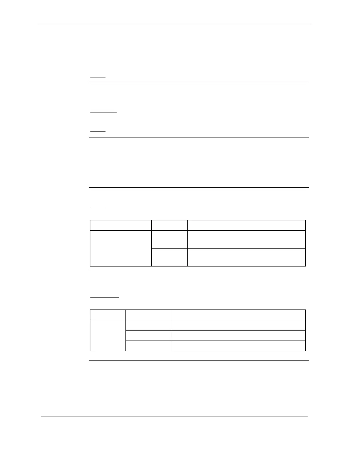
Table: JP4 -
Watchdog
Enable/Disable
This two-position jumper enables or disables the hardware Watchdog.
Note: Never leave the Watchdog disabled during normal D20 ME
operation.
Jumper Position Function
pin 1 to 2
(center)
Disables the hardware Watchdog. JP4
Pin 1 = SLOWCK
Pin 3 = /WD
pin 3 to 2
(center)
Enables the hardware Watchdog.
Table: JP8 –
Battery Backup
Enable/Disable
The D20 ME card has two 3.6V Lithium batteries, TADIRAN
TM
TL-2150 or
equivalent, to maintain NVRAM contents in the event of a power failure.
Important: Disconnect the batteries if you are storing the board for extended
periods of time.
Jumper Position Function
pin 1 to 2 Disconnects the batteries from the NVRAM
pin 3 to 2 Connects the batteries to the NVRAM
JP8
pins 4 to 5 Always jumpered
994-0025-1.00-8 General
6
Full Release