3-36 D30 Line Distance Protection System GE Multilin
3.3 DIRECT INPUT/OUTPUT COMMUNICATIONS 3 HARDWARE
3
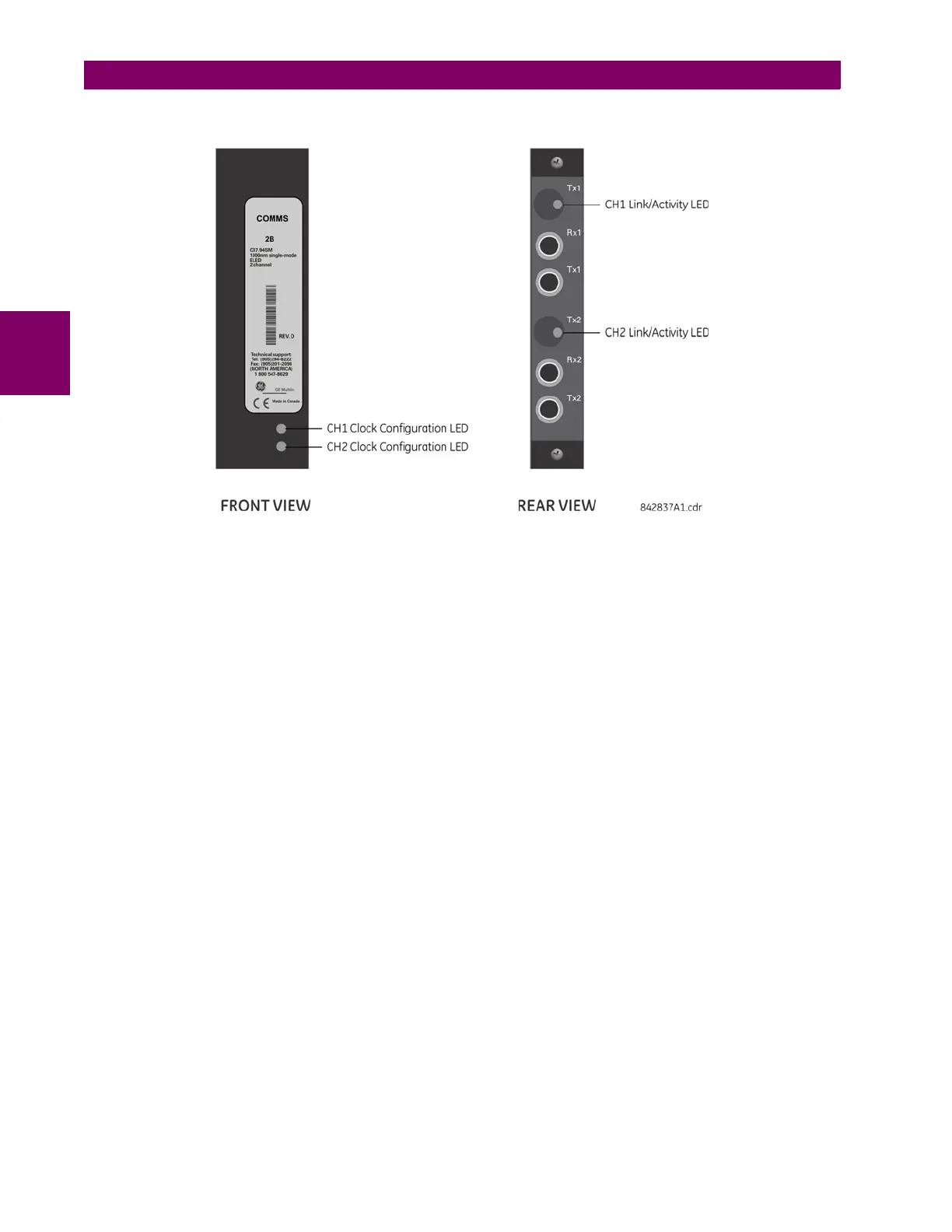
Modules shipped since January 2012 have status LEDs that indicate the status of the DIP switches, as shown in the follow-
ing figure.
Figure 3–44: STATUS LEDS
The clock configuration LED status is as follows:
• Flashing green — loop timing mode while receiving a valid data packet
• Flashing yellow — internal mode while receiving a valid data packet
• Solid red — (switch to) internal timing mode while not receiving a valid data packet
The link/activity LED status is as follows:
• Flashing green — FPGA is receiving a valid data packet
• Solid yellow — FPGA is receiving a "yellow bit" and remains yellow for each "yellow bit"
• Solid red — FPGA is not receiving a valid packet or the packet received is invalid


 To Next Page