EasyManuals Logo

GE GEH-6285C User Guide

GE GEH-6285C
27 pages
To Next Page IconTo Next Page
To Previous Page IconTo Previous Page
Page #8 background imageLoading...
Page #8 background image
Power
Break
®
II
Circuit
Breakers
Chapter
1
.
Introduction
4
jl
1
-
3
Preparation
for
Installation
1
-
1
Overview
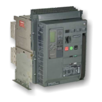
Power
Break
®
II
insulated
-
case
circuit
breakers
are
designed
to
protect
low
-
voltage
power
circuits
and
equipment
.
They
are
available
with
MicroVersa
-
Trip
®
Plus
and
PM
Trip
Units
for
fault
detection
.
Electrical
Connections
Using
an
industry
-
accepted
solvent
,
remove
any
foreign
material
from
the
line
and
load
strap
sur
-
faces
and
the
corresponding
surfaces
of
the
con
-
necting
bus
.
Ensure
that
the
mating
surfaces
are
smooth
and
free
of
burrs
and
nicks
.
Place
the
bus
connections
in
position
and
align
the
mounting
holes
.
Insert
and
fasten
the
mounting
bolts
and
washers
according
to
specifications
in
Table
2
.
1
-
2
Receiving
the
Breaker
Unpack
the
circuit
breaker
and
inspect
it
for
ship
-
ping
damage
.
Ensure
that
the
breaker
has
the
proper
current
,
voltage
,
and
interruption
ratings
for
the
application
by
comparing
the
catalog
number
with
the
table
in
the
Getting
Started
section
on
the
inside
front
page
.
The
weights
of
the
various
frame
sizes
are
listed
in
Table
1
,
for
reference
.
Bus
Connection
Breaker
Frame
Bolt
Diam
.
Torque
(
in
-
lb
)
(
1
)
1
/
2
in
.
300
800
A
Operation
Type
Frame
Rating
Weight
(
2
)
l
/
2
in
.
1600
-
2000
A
300
(
ib
.
)
Table
2
.
Bolt
sizes
and
mounting
torques
for
bus
connections
.
71
800
A
Manual
Electrical
80
Panel
Cutouts
and
Clearances
Use
the
following
information
to
prepare
the
equipment
and
assure
proper
clearances
for
instal
-
lation
and
operation
of
the
breaker
.
Figure
1
shows
the
front
-
panel
escutcheon
cutout
pattern
and
the
locations
of
the
breaker
mounting
bolts
.
The
standard
door
cutout
dimensions
require
a
trim
plate
on
the
breaker
.
The
optional
dimen
-
sions
are
for
flush
front
or
non
-
hinged
door
con
-
struction
and
the
trim
plate
may
be
omitted
.
Venti
-
lation
cutouts
are
required
for
stationary
-
mounted
1600
A
and
2000
A
frame
breakers
and
for
draw
-
out
-
mounted
2000
A
frame
breakers
.
Ventilation
cutouts
are
not
required
for
drawout
-
mounted
800
A
or
1600
A
frame
breakers
or
for
stationary
-
mounted
800
A
frame
breakers
.
Because
of
arc
chamber
venting
,
the
minimum
through
-
air
distance
from
the
top
of
the
breaker
s
molded
case
to
grounded
metal
is
4
50
inches
[
114
mm
]
in
an
area
5.31
inches
x
16.00
inches
[
135
mm
x
406
mm
]
,
centered
over
the
vent
screens
.
(
Refer
to
outline
drawings
10054370
,
Sheets
1
-
5
,
for
details
.
)
79
2000
A
Manual
Electrical
88
Table
1
.
Weights
of
various
breaker
frame
sizes
,
with
and
without
motor
operator
;
Storage
The
breaker
should
be
placed
in
service
immedi
-
ately
in
its
permanent
location
.
However
,
if
it
must
be
stored
for
an
indefinite
period
,
it
should
be
care
-
fully
protected
against
condensation
,
preferably
by
storage
in
a
warm
dry
room
.
Circuit
breakers
for
outdoor
equipment
should
be
stored
in
that
equip
-
ment
only
when
power
is
available
and
heaters
are
in
operation
,
to
prevent
condensation
.
The
breaker
should
be
stored
in
a
clean
location
,
free
from
corrosive
gases
or
fumes
.
In
particular
,
protect
the
breaker
from
moisture
and
cement
dust
,
as
that
combination
may
be
corrosive
.
If
the
breaker
is
stored
for
any
length
of
time
,
it
should
be
inspected
periodically
to
ensure
good
mechanical
condition
.
i
Courtesy of NationalSwitchgear.com

Other manuals for GE GEH-6285C

Questions and Answers:

Question and Answer IconNeed help?

Do you have a question about the GE GEH-6285C and is the answer not in the manual?

GE GEH-6285C Specifications

General IconGeneral
BrandGE
ModelGEH-6285C
CategoryCircuit breakers
LanguageEnglish

Related product manuals