66
Drain Pump
Operating Voltage: 120 VAC
Resistance: 14.8 Ω
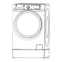
Drain Pump Location (Front View)
Recirculation Pump
Drain Pump
Drain pump operation is controlled by a relay on the
IMC board. The drain pump will be energized any
time the pressure sensor frequency reads above the
overfl ow level.
Drain Pump Strip Circuit
IMC J701-4
D
To Neutral
IMC J101-2
Drain Pump
Switched L1
Drain Pump Tests
1. Enter service mode.
2. Run Test 12.
3. Press the Start key to begin the test.
4. The door locks and the cold water valve is turned
on. The control will fi ll to the main water level, and
then turn off the valve.
Drain Pump Diagnostics
5. Check for current draw at IMC J701-4.
a. If current draw is detected and water is not
draining, check for foreign material in pump
and pump fi lter.
b. If no current draw is detected, go to step 2.
6. Check for 120 VAC between IMC J701-4 and IMC
J101-2.
a. If 120 VAC is not present replace the IMC
board.
b. If 120 VAC is present check wiring between
IMC board and pump. If wiring is ok replace
pump.
Drain Pump Removal
1. Disconnect power to the unit.
2. Open the pump clean out and drain excess water.
3. Remove the control panel. (See Control Panel
Removal)
4. Remove the front panel. (See Front Panel Re-
moval)
5. Remove the wire harnesses from the drain pump
and recirculation pump (if present).
Drain Pump Harness
Recirc Pump Harness
6. Remove the right front top damper pin and push
the damper aside.
7. Remove the drain pump hose.
8. Remove the recirculation pump hose (if present).
9. Remove the 5/16” sump hose clamp and remove
Wash System
 Loading...