49-1000399 Rev. 2 13
8QVQDSWKHFOHDUSODVWLFFRYHUIURPWKHWHUPLQDOEORFNWRDFFHVVWHUPLQDOVFUHZV
Loosen the supply side terminal screws on the lower side of the block with a Phillips
screwdriver. Attach supply wires to the appropriate polarity and ground terminals
as indicated on label: connect positive wire to terminal marked +, negative wire to
WHUPLQDOPDUNHGDQGJURXQGWRWHUPLQDOPDUNHG*1'5HWLJKWHQWHUPLQDOEORFN
screws and replace clear plastic cover.
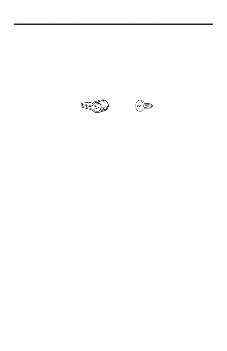
• A wiring strain relief clip must be installed for the supply wires. From the selection
RIZLUHFOLSVSURYLGHGLQWKH2ZQHU¶V0DQXDOEDJVHOHFWWKHDSSURSULDWHVL]HFOLS
needed to fit the supply wires used.
8VHWKHVFUHZDOVRSURYLGHGLQWKH2ZQHU¶V0DQXDOEDJWRPRXQWWKHVWUDLQUHOLHI
clip at the location shown on the bottom rail of the compressor compartment. The
wires must be completely snug after clip is installed with no movement or slippage of
the wires within the clip when the wires are tugged.
• Replace the rear unit cover, routing the supply wires through the opening provided.
• Move unit into its final position taking care not to roll over or damage the main power
supply line.
$IWHUFRPSOHWLQJLQVWDOODWLRQHQHUJL]HWKHDSSOLDQFHE\UHSODFLQJUHIULJHUDWRUFLUFXLW
IXVHRUWXUQLQJRQFLUFXLWEUHDNHULQWKH'&YROWDJHGLVWULEXWLRQSDQHO5HWXUQWKH
FRQWURONQREWRWKH&2/'SRVLWLRQ
Electrical Connection (Cont.)
Installation Instructions